
radio
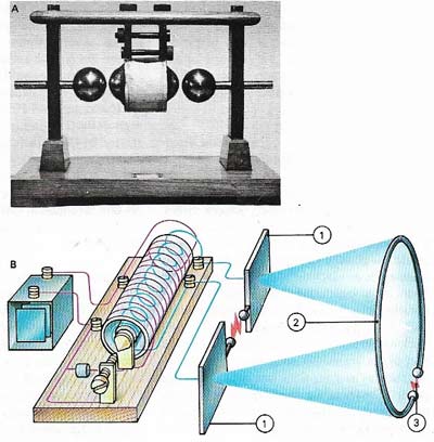
Figure 1. The first radio transmitters (A), as used by Heinrich Hertz and Oliver Lodge, made use of the radio waves generated when a high-voltage spark jumped between contacts (B). Hertz beamed the waves from aerial plates (1) and detected them with a loop of wire (2) in which they caused a small spark to jump a gap (3).
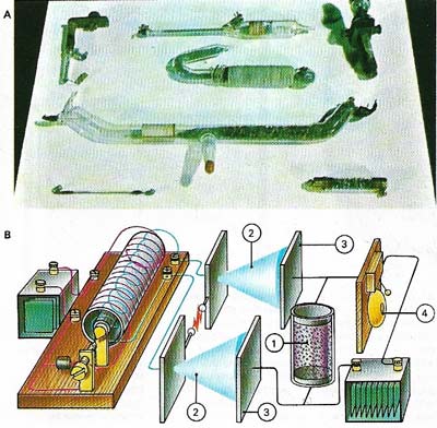
Figure 2. The first practical radio detectors were coherers (A), developed by Oliver Lodge (1851–1940). Each of those shown consists of a long glass tube with iron filings packed between two metal plates. In their loose condition the filings did not conduct electricity but when subjected to a vibrating electric wave they cohered (adhered to each other), making a conducting path between the plates. In the circuit shown (B) the coherer (1) acts as a switch in an electric bell circuit. As soon as streams of radio waves (2) reach the aerial plates (3), the coherer filings adhere, thus ringing the bell (4).Radio galaxy 3C305.
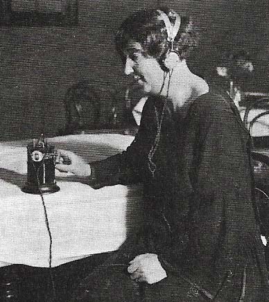
Figure 3. A 1920s crystal set, forerunner of the modern transistor, used a crystal of carborundum or lead sulfide, a semiconductor that rectified a radio carrier wave. This crystal produced an alternating current of the same frequency as the sound "carried" on the wave. The low frequency electric current had sufficient power to produce sound from sensitive earphones.
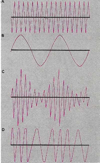
Figure 4. Radio waves have high frequencies (A), whereas sound waves have very much lower frequencies (B). To transmit sound by radio it is necessary to superimpose the sound frequency on to a radio wave. Because this radio wave carries the electrical analog of the original sound, it is called the carrier wave. Amplitude modulation (AM) modifies the energy level of the individual carrier waves to produce an "envelope" of varying amplitude (C) corresponding to the sound waves. In frequency modulation (FM), the carrier amplitude is kept constant, the wave's frequency being increased or reduced to produce a frequency analogue of the sound (D).
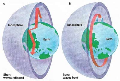
Figure 5. The ionosphere (a layer of ionized gas in the Earth's upper atmosphere) and the curved surface of the Earth below act together as a kind of wave-guide, which bends the path of long radio waves (B) around the Earth. The path of waves of the medium band is not as bent, which is why they cannot normally be received more than a few hundred kilometers from the transmitter. All radio waves travel strictly in straight lines in free space but short waves are used for round-the-world communication because they are reflected by the ionosphere and also by the Earth's surface, as though these were mirrors (A). Even short waves pass through the ionosphere and so are used for space communications.
Radio is the communication of information between distant points using radio waves, electromagnetic radio of wavelength between about 1 millimeter and 100 kilometers. Radio waves are also described in terms of their frequency – measured in hertz (Hz) and found by dividing the velocity of the waves (about 300 million meters/second) by their wavelength.
Radio communications system link transmitting stations with receiving stations. In a transmitting station a piezoelectric oscillator is used to generate a steady radio-frequency (RF) carrier wave. This is amplified and modulated (see modulation) with a signal carrying the information to be communicated. The simplest method of modulation is to pulse (switch on and off) the carrier with a signal in, say, Morse code, but speech and music, entering the modulator as an audio-frequency (AF) signal from tape of a microphone, is made to interact with the carrier so that the shape of the audio wave determines either the amplitude of the carrier wave (amplitude modulation, AM) or its frequency within a small band on either side of the original carrier frequency (frequency modulation, FM). The modulated RF signal is then amplified (see amplifier) to a high power and radiated from an antenna. At the receiving station, another antenna picks up a minute fraction of the energy radiated from the transmitter together with some background noise. The RF signal is amplified and the original audio signal is recovered (demodulation or detection). Detection and amplification often involve many stages including feedback and intermediate frequency (IF) circuits. A radio receiver must of course be able to discriminate between all the different signals acting at any one time on its antenna. This is accomplished with a tuning circuit which allows only the desired frequency to pass to the detector.
In point-to-point radio communications most stations can both transmit and receive messages but in radio broadcasting a central transmitter broadcasts program sequences to a multitude of individual receivers. Programs are often produced centrally and distributed to a "network" of local broadcasting stations by wire or microwave link. Because there are potentially so many users of communications – aircraft, ships, police, amateur"hams" as well as broadcasting services – the use of the RF portion of the electromagnetic spectrum is strictly controlled to prevent unwanted interference between signals having adjacent carrier frequencies. The International Telecommunication Union (ITU) and national agencies such as the US Federal Communications Commission (FCC) divide the RF spectrum into bands which it allocates to the various users. Public broadcasting in the US uses MF frequencies between 535 kHz and 1605 kHz (AM) and VHF bands between 88 MHz and 108 MHz (FM). VHF reception, though limited to line-of-sight transmissions, offers much higher fidelity of transmission and much greater freedom from interference. International broadcasting and local transmissions in other countries often use other frequencies in the LF, MF, and HF (short wave) bands.
Development of radio
The existence of radio waves was first predicted by James Clerk Maxwell in the 1860s but it was not until 1887 that Hertz succeeded in producing them experimentally. "Wireless" telegraphy was first demonstrated by Oliver Lodge in 1894 and Marconi made the first transatlantic transmission in 1901. Voice transmission was first achieved in 1900 but transmitter and amplifier powers were restricted before the invention of Lee de Forest's triode electron tube in 1906. Only the development of the transistor after 1948 had a great impact on radio technology. Commercial broadcasting began in the US in 1920.
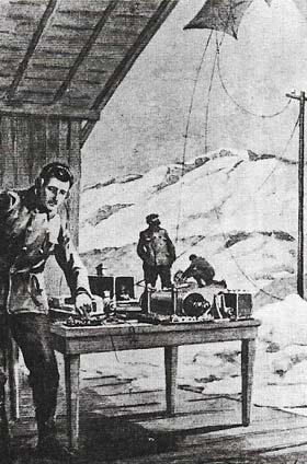 |
| Three dots – the Morse code "S" – signaled success for Guglielmo Marconi and for the future of wireless telegraphy in 1901. They were transmitted from Cornwall, England, and received 3,520 km (2,200 miles) away in Newfoundland by the inventor himself. The transmitter, using electricity generated by a 25hp oil engine, had an aerial supported by four 61 m (200 ft) masts. Marconi's receiver was connected to a 122 m (400 ft) aerial supported by a kite. Marconi had proved to doubting science his firm belief that radio waves were capable of travelling around the curvature of the Earth. |
Radio beacon
A radio beacon is a navigational aid for ships and aircraft. It consists of a transmitter that broadcasts radio signals of a fixed frequency, peculiar to one beacon only. A navigator or pilot, by referring to navigation charts, can find his or her position from the bearings of two or more beacons, using a directional antenna to receive the signals.

