
axial-flow compressor
An axial-flow compressor is a type of compressor in which the working fluid, such as air, is compressed in a series of stages as it flows axially (parallel with the axis of rotation), through a decreasing tubular area. Axial compressors are widely used in gas turbines, such as those in jet engines, high speed ship engines, and small scale power stations. They are also used in industrial applications such as large volume air separation plants, blast furnace air, fluid catalytic cracking air, and propane dehydrogenation.
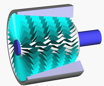
An axial-flow compressor compresses its working fluid by first accelerating the fluid and then diffusing it to obtain a pressure increase. The fluid is accelerated by a row of rotating airfoils (blades) called the rotor, and then diffused in a row of stationary blades (the stator). The diffusion in the stator converts the velocity increase gained in the rotor to a pressure increase.
An axial-flow compressor consists of several stages: 1) A combination of a rotor followed by a stator make-up a stage in a compressor; 2) An additional row of stationary blades are frequently used at the compressor inlet and are known as inlet guide vanes to ensue that air enters the first-stage rotors at the desired flow angle, these vanes are also pitch variable thus can be adjusted to the varying flow requirements of the engine; and 3) In addition to the stators, another diffuser at the exit of the compressor consisting of another set of vanes further diffuses the fluid and controls its velocity entering the combustors and is often known as the exit guide vanes.
Air passes from one stage to the next, each stage raising the pressure slightly. By producing low-pressure increases on the order of 1.1:1 to 1.4:1, very high efficiencies can be obtained as seen in table 1. The use of multiple stages permits overall pressure increases of up to 40:1 in some aerospace applications and a pressure ratio of 30:1 in some industrial applications.