
DC circuits
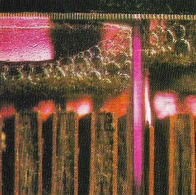
Figure 1. A cell or battery sends electrons round an electrical circuit as a result of chemical action. This unidirectional character of the electron flow is called direct current (DC), even if it varies greatly or stops altogether from time to time. In a primary cell current flow stops as soon as one of the chemicals or electrodes is consumed. A secondary cell or accumulator can be recharged, often forming these gas bubbles.
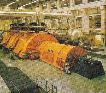
Figure 2. Electrical generators can be AC or DC machines. The output of a DC machine does not depend on an exhaustible chemical process, so it usually gives a steadier direct current than chemical sources. Large generators like these supply alternating current (AC), characterized by a rapid periodic reversal of electron flow. In an AC system the current falls to zero every time the direction of its flow is reversed.
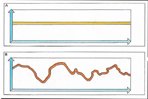
Figure 3. A method of examining direct current is to measure how it varies over a fixed period. Graph A shows a current, such as that taken by a lamp supplied by a generator, which does not alter over the time it is measured (the vertical axis represents current and the horizontal one time). Graph B shows a direct current typical of a welding circuit. It varies with time, although its value is always positive.
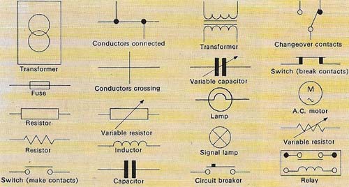
Figure 4. The drawings used by engineers and other workers in the electrical industry have to be clear to the reader irrespective of his language. These symbols are just a few of the hundreds used.
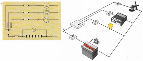
Figure 5. This diagram of a circuit (A) shows a typical but simplified electrical system (B) of the kind that is used for equipment powered by a battery. Switches control the current flow into three leads to a lamp and two appliances containing electric motors. The voltmeter records the electromotive force (that is, the voltage) of the battery, which remains virtually constant. The current flowing through the lamp will also remain virtually constant, but those through the appliances may vary, depending on the demands made by the motors in them. Fuses can protect the circuit from current surges.
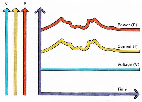
Figure 6. The circuit shown in illustration 6 has many interdependent electrical variables. Representing them in the form of a graph indicates how they are related. (There are different scales on the vertical axes but the horizontal axis, time, is the same for all the other variables.) Three of the most important variables – voltage, current, and power – are shown. The current (I) is fixed by the battery. If the battery is in good condition the voltage will not vary significantly. The voltage (V) depend on the voltage and the resistance of the appliance it is feeding. This may vary (as it does in the motors) or may be fixed (as it is in the lamp). The power (P) is the product of voltage and current and is measured in watts.
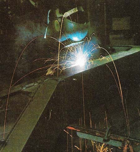
Figure 7. Welding is a process of joining metals together with a bond so strong that it is often superior to the parent materials. A large electric current – perhaps 2,000 amps – at low voltage can be used to provide the necessary heat, so that the metal in a particular area is melted. The current passes in the form of an arc from an insulated electrode in the welder's hand and enters the work-piece across a short air gap. The object that is to be welded is connected to one terminal of the cur-rent source and the welding electrode to the other. Electric welding generally uses direct current, generated by special equipment because of the very large currents needed.
An electrical circuit is the system by which an electric current is directed, controlled, modified, switched on or switched off. Circuits can contain from two or three to many hundred different components, according to the way in which the current is to be controlled, but all share certain characteristics.
The formation of a circuit
The primary requirement of a circuit is that it must forma complete path; electrons must be able to flow round the whole system so that as many electrons pass back into the source of the current as leave it. Certain occurrences, such as lightning strikes or electric shocks, seem to deny this first requirement, but are nevertheless examples of electrical circuits. This apparent contradiction can be resolved by considering the Earth and all the structures on it as a vast electron bank. If clouds develop an electron imbalance, the earth makes it up with a flash of lightning and the net result is that on average the numbers of electrons leaving the earth and arriving at it are equal.
Electric currents can also be "carried" by charged atoms, or ions. Ions of dissolved salts and other chemicals conduct current through the electrolyte in an electroplating bath and gas ions conduct electricity in a fluorescent strip-light. But whatever the current carriers, all circuits share three characteristics: a current (I), a voltage (V) and a resistance (R).
An illustration of electron movement (and the use of high-voltage direct current) is the arrangement of the transmission line from the Cabora Bassa dam in Mozambique to the South African town of Apollo some 500 kilometers (310 miles) away. There are two lines to carry the current, one taking electrons to Apollo, the other returning the same number to Cabora Bassa. If one of the lines breaks, the earth itself "replaces" it and carries the electrons in the appropriate direction.
In a similar way, the chassis of vehicles are used as the so-called earth or return circuit, although this is a loose and generally inaccurate term. One terminal of the battery is connected to the bodywork and a single wire is brought from the other terminal through a switch to each piece of electrical equipment. These in turn are also connected firmly to the chassis. The circuit so established allows the number of electrons leaving the battery to be matched exactly, by the number of those arriving. Using the chassis to complete the circuit in this way makes a second wire to each component unnecessary.
Direct and alternating current
One major practical difference in circuit components (although there are no differences in principle) is determined by whether they are used for direct current or alternating current. Direct current is unidirectional; the electron flow is always in the same direction and although it may stop and start, grow or diminish in quantity, it never reverses.
Current flow (as opposed to electron flow, which is always against the conventional direction of current flow) is assumed by convention to be from a positive to a negative terminal. In direct correct (DC) generators, batteries and some other sources, the terminals are determined by the nature of the machine or equipment and are irreversible. The most common example of direct current source is a chemical cell or battery, in which the nature of the chemicals themselves fixes the polarity of the system. Although the output of the cell may vary, the current flow is always in the same direction. The same applies to a DC generator (dynamo), because the structure of the machine determines the polarity. Another device, known as a rectifier, also has fixed polarity. A rectifier is used to convert alternating current to direct current – irrespective of how the input varies, the current direction at the output terminals is always the same.
Alternating current (AC) is the more common mode, although in certain instances direct current is particularly appropriate and alternating current cannot be used. In electroplating, for example, direct current is used because it is vital that the current always flows in the same direction. If it did not, material would pass back and forth from the coating metal to the coated surface and no plating would take place. The recharging of a battery (Figure 1), which is a specialized form of "electroplating", can also be carried out only by direct current and mains-powered battery chargers must contain a rectifier.
In systems for transmitting power over long distances, direct current may be chosen because it requires less insulation and uses fewer and narrower conductors for the amount of power transmitted than does alternating current. Direct current, provided it is steady, uses its conductors fully throughout the whole of the transmission period whereas the conductors of an alternating current are not always fully utilized. As a result, a smaller conductor can be used for the same effective power transmission and if the current is to be transmitted over very long distances the savings may be considerable.
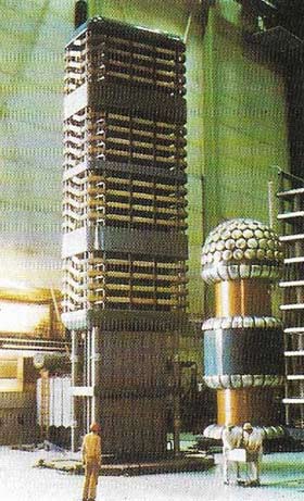 |
| It is often economical to use direct current at high voltage when transmitting large amounts of electrical power. Reliable equipment is available to switch large DC voltages on and off. This large thyristor "switch" operates on similar principles to transistors used in radios. Because power stations are being sited farther away from population centers, high voltage DC is increasingly used instead of AC. |
Interrupting the flow
Despite some advantages, the use of direct current is beset by one major problem: switching it off quickly. Interrupting a current that is flowing tends to produce a spark between the contacts providing the interruption. Sometimes this can take the form of a spark so large that it melts not only the contacts but the switching device itself. Alternating current, by its very nature, falls to zero many times a second, so that the spark also falls to zero, limiting the damage it can do.

