
fuel cell
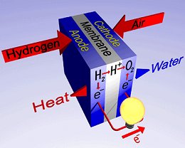
Principle of a fuel cell.
A fuel cell is an electrochemical system in which the chemical energy of a fuel is converted directly into electrical energy. A fuel cell works in a similar way to a primary battery with the difference that the energy is not stored between the electrodes, but is instead transferred from an external tank. Because there is no combustion, fuel cells give off few emissions. Also, having no moving parts, they are quiet.
Fuel cell technology dates back to the 1800s, but it wasn't until the end of the 20th century that it was used successfully in spacecraft to provide electricity and water. The technology can be used to make electricity to power vehicles, homes, and businesses. And if a renewable energy source is used as the main source of hydrogen, a fuel cell can be considered a renewable energy source.
Today the technology is used for the production of electric and thermal energy in power-heat coupling systems (see block-type thermal power station) and it is also the source of electricity in electric automobiles. Unlike battery-powered electric automobiles, fuel cell powered automobiles achieve similar ranges and load-carrying capacities to conventional automobiles with combustion engines. In the past few decades, significant advances in the materials sciences have helped spur the breakthrough of fuel cell technology.
How fuel cells work
Unlike conventional technologies, fuel is not "burned" but is combined in a chemical process. A fuel cell consists of two electrodes sandwiched around an electrolyte. Oxygen passes over one electrode and hydrogen over the other, generating electricity, water, and heat.
Hydrogen fuel is fed into the anode of the fuel cell. Oxygen (or air) enters the fuel cell through the cathode. Encouraged by a catalyst, the hydrogen atom splits into a proton and an electron, which take different paths to the cathode. The proton passes through the electrolyte. The electrons create a separate current that can be utilized before they return to the cathode, to be reunited with the hydrogen and oxygen in a molecule of water.
A fuel cell system that includes a fuel reformer can obtain hydrogen from any hydrocarbon fuel – from natural gas, methanol, and even gasoline. Other possible fuels include propane, hydrogen, anaerobic digester gas from wastewater treatment facilities, and landfill gas.
Fuel cell types
Fuel cells are categorized according to the type of electrolyte used. Some of the these include:
All three of the above fuel cell types operate at temperatures that require that conversion of fuel to hydrogen occur outside of the fuel cell. This approach introduces a level of complexity avoided by the following two fuel cell designs:
See also regenerative fuel cell.
Parts of a fuel cell
Polymer electrolyte membrane (PEM) fuel cells are the current focus of research for fuel cell vehicle applications. PEM fuel cells are made from several layers of different materials, as shown in the diagram. The three key layers in a PEM fuel cell include
Other layers of materials are designed to help draw fuel and air into the cell and to conduct electrical current through the cell.
Membrane electrode assembly
The electrodes (anode and cathode), catalyst, and polymer electrolyte membrane together form the membrane electrode assembly (MEA) of a PEM fuel cell.
The thickness of the membrane in a membrane electrode assembly can vary with the type of membrane. The thickness of the catalyst layers depends upon how much platinum (Pt) is used in each electrode. For catalyst layers containing about 0.15 milligrams (mg) Pt/cm2, the thickness of the catalyst layer is close to 10 micrometers (μm) – less than half the thickness of a sheet of paper. This membrane/electrode assembly, with a total thickness of about 200 μm (or 0.2 mm), can generate more than half an ampere of current for every square centimeter of assembly area at a voltage of 0.7 volts, but only when encased in well-engineered components – backing layers, flow fields, and current collectors.
Catalyst
All electrochemical reactions in a fuel cell consist of two separate reactions: an oxidation half-reaction at the anode and a reduction half-reaction at the cathode. Normally, the two half-reactions would occur very slowly at the low operating temperature of the PEM fuel cell. Each of the electrodes is coated on one side with a catalyst layer that speeds up the reaction of oxygen and hydrogen. It is usually made of platinum powder very thinly coated onto carbon paper or cloth. The catalyst is rough and porous so the maximum surface area of the platinum can be exposed to the hydrogen or oxygen. The platinum-coated side of the catalyst faces the PEM. Platinum-group metals are critical to catalyzing reactions in the fuel cell, but they are very expensive. DOE's goal is to reduce the use of platinum in fuel cell cathodes by at least a factor of 20 or eliminate it altogether to decrease the cost of fuel cells to consumers.
Hardware
 |
| Magnified image of catalyst in contact with the solid
polymer electrolyte membrane of a fuel cell. The catalyst is rough
and porous so that the maximum surface area of the platinum can be
exposed to the hydrogen or oxygen. The platinum-coated side of the
catalyst faces the PEM.
|
The backing layers, flow fields, and current collectors are designed to maximize the current from a membrane/electrode assembly. The backing layers – one next to the anode, the other next to the cathode – are usually made of a porous carbon paper or carbon cloth, about as thick as 4 to 12 sheets of paper. The backing layers have to be made of a material (like carbon) that can conduct the electrons that leave the anode and enter the cathode. The porous nature of the backing material ensures effective diffusion (flow of gas molecules from a region of high concentration to a region of low concentration) of each reactant gas to the catalyst on the membrane/electrode assembly. The gas spreads out as it diffuses so that when it penetrates the backing, it will be in contact with the entire surface area of the catalyzed membrane.
The backing layers also help in managing water in the fuel cell; too little or too much water can cause the cell to stop operating. Water can build up in the flow channels of the plates or can clog the pores in the carbon cloth (or carbon paper), preventing reactive gases from reaching the electrodes.
The correct backing material allows the right amount of water vapor to reach the membrane/electrode assembly and keep the membrane humidified. The backing layers are often coated with Teflon to ensure that at least some, and preferably most, of the pores in the carbon cloth (or carbon paper) do not become clogged with water, which would prevent the rapid gas diffusion necessary for a good rate of reaction at the electrodes.
Pressed against the outer surface of each backing layer is a piece of hardware called a bipolar plate that typically serves as both flow field and current collector. In a single fuel cell, these two plates are the last of the components making up the cell. The plates are made of a lightweight, strong, gas-impermeable, electron-conducting material – graphite or metals are commonly used even though composite plates are now being developed.
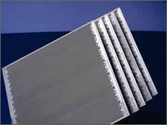 |
| Photograph of the bipolar plates that serve as both
flow field and current collectors in PEM fuel cells. The plates are
made of a lightweight, strong, gas-impermeable, electron-conducting
material-graphite or metals are commonly used, although composite
plates are now being developed.
|
The first task served by each plate is to provide a gas "flow field." Channels are etched into the side of the plate next to the backing layer. The channels carry the reactant gas from the place where it enters the fuel cell to the place where it exits. The pattern of the flow field in the plate (as well as the width and depth of the channels) has a large impact on how evenly the reactant gases are spread across the active area of the membrane/electrode assembly. Flow field design also affects water supply to the membrane and water removal from the cathode.
Each plate also acts as a current collector. Electrons produced by the oxidation of hydrogen must (1) be conducted through the anode, through the backing layer, along the length of the stack, and through the plate before they can exit the cell; (2) travel through an external circuit, and (3) re-enter the cell at the cathode plate. With the addition of the flow fields and current collectors, the PEM fuel cell is complete; only a load-containing external circuit, such as an electric motor, is required for electric current to flow.
Fuel cell technology challenges
Cost and durability are the major challenges to fuel cell commercialization. However, hurdles vary according to the application in which the technology is employed. Size, weight, and thermal and water management are barriers to the commercialization of fuel cell technology. In transportation applications, these technologies face more stringent cost and durability hurdles. In stationary power applications, where cogeneration of heat and power is desired, use of PEM fuel cells would benefit from raising operating temperatures to increase performance. The key challenges include: