
Integrated Truss Structure
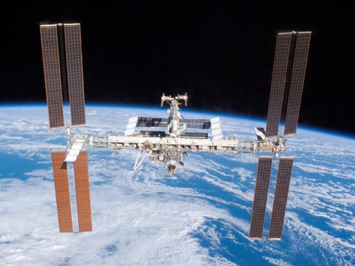
The International Space Station in June 2007. Credit: NASA.
S0 Truss
Shuttle Mission: STS-110ISS Assembly Mission: 8A
Dimensions: 13.4 meters × 4.6 meters (44 feet × 15 feet)
Weight: 13,971 kilograms (30,800 pounds)
The S0 Truss, the center segment of 11 integrated trusses, was attached to the top of the Destiny Laboratory on 11 April 2002. The S0 Truss acts as the junction from which external utilities are routed to the International Space Station's pressurized modules. These utilities include power, data, video and ammonia for the Active Thermal Control System. The truss also provides a mounting point for electronic equipment such as the Main Bus Switching Units, four of the DC-to-DC Converter Units and four Secondary Power Distribution Assemblies. Also mounted on S0 are the station's four GPS antennas and two Rate Gyros.
The rear of the S0 Truss is occupied by a 6.4-meter (21-foot) radiator panel, which radiates heat transported from the truss' electronics boxes. The forward-facing rails of the S0 Truss and the other 10 truss assemblies form a track upon which the Mobile Transporter can move to different robotic arm worksites along the integrated truss structure.
S1 Truss
Shuttle Mission: STS-112
ISS Assembly Mission: 9A
Dimensions: 13.7 meters × 4.6 meters × 1.8 meters (45 feet ×
15 feet × 6 feet)
Weight: 14,124 kilograms (31,137 pounds)
The S1 Truss, the first starboard truss segment, was attached to the starboard side of the S0 Truss 10 October 2002. The S1 Truss provides structural support for the Active Thermal Control System, Mobile Transporter and one Crew and Equipment Translation Aid cart. The cart is manually operated by a spacewalker and can also be used as a work platform. The cooling system is like the one in a car radiator except that it uses 99.9% pure ammonia, compared to 1% in household products. The Thermal Radiator Rotary Joint rotates the three radiator structures in a 105-degree span either way to keep the three radiators panels in the shade; it also transfers power and ammonia to the radiators. The S1 Truss also has mounts for cameras and lights, as well as antenna support equipment for S-band communications equipment.
S3/S4 Truss
Shuttle Mission: STS-117
ISS Assembly Mission: 13A
The second starboard truss segment, the S3/S4 Truss, is attached to the first starboard truss segment, the S1.
S5 Truss
Shuttle Mission: STS-118
ISS Assembly Mission: 13A.1
The third starboard truss segment, the ITS S5 Truss, is attached to the S3/S4 Truss.
S6 Truss
Shuttle Mission: STS-119
ISS Assembly Mission: 15A
Fourth starboard truss segment, the S6 Truss, is delivered.
P1 Truss
Shuttle Mission: STS-113
ISS Assembly Mission: 11A
Dimensions: 13.7 meters × 4.6 meters × 1.8 meters (45 feet ×
15 feet × 6 feet)
Weight: 14,003 kilograms (30,871 pounds)
The P1 Truss, the first port truss segment, was attached to the port side of the S0 truss 26 November 2002. The P1 Truss provides structural support for the Active Thermal Control System, Mobile Transporter and one Crew and Equipment Translation Aid cart. The cart is manually operated by a spacewalker and can also be used as a work platform. The cooling system is like a car radiator except that it uses 99.9% pure ammonia, compared to 1% in household products. The Thermal Radiator Rotary Joint rotates the three radiator structures in a 105-degree span either way to keep the three radiators panels in the shade; it also transfers power and ammonia to the radiators. The P1 Truss also has mounts for cameras and lights, and antenna support equipment for both UHF and S-band communications equipment. The S-band equipment is currently on the P6 Truss.
P3/P4 Truss
Shuttle Mission: STS-115
ISS Assembly Mission: 12A
Delivers the second port truss segment, the P3/P4 Truss, to attach to the first port truss segment, the P1 Truss.
P5 Truss
Shuttle Mission: STS-116
ISS Assembly Mission: 12A.1
Delivers third port truss segment, the P5 Truss, to attach to second port truss segment, the P3/P4 Truss.
P6 Truss
Delivery Configuration
Shuttle Mission: STS-97
ISS Assembly Mission: 4A
Temporarily installed on the Z1 truss during STS-97, the P6 integrated truss structure (ITS) will be relocated to its permanent location on the P5 truss during a later assembly mission. The four primary functions of the P6 are the conversion or generation, storage, regulation and distribution of electrical power for the space station. The station derives its power from the conversion of solar energy into electrical power. The P6 Photovoltaic Power Module performs this energy conversion.
Permanent Configuration
Shuttle Mission: STS-120
ISS Assembly Mission: 10A
Delivers Node 2.
Z1 Truss
Shuttle Mission: STS-92
ISS Assembly Mission: 3A
ITS Z1 was an early exterior framework to allow first US solar arrays on flight 4A to be temporarily installed on Unity for early power.

