
metalworking machines
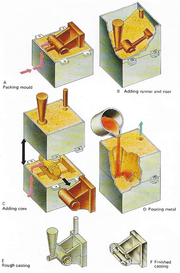
Figure 1. Sand casting is the most widely used casting method. A wooden pattern is made up from the original design, then packed with sand up to its largest cross-sectional area in a steel box (A). The top part or the mould is assembled. It is clamped on to the bottom box and more sand rammed into it. A wooden runner and riser are fixed in position (B). The sand core for a hollow in the casting is made. The sand for this is mixed with sodium silicate which forms "silicate gel" when carbon dioxide is pumped through it. This "gel" has a syrupy consistency and binds the sand together. The mould is split and pattern removed. The core is placed in position and the mould assembled (C). Runner and riser are removed. Molten metal is poured into the dried mould through the conical-shaped runner. Displaced air escapes through the riser (D). After cooling, the mould is split open and the casting removed (E). The runner and riser are cut off and the sand core is knocked out. The finished casting (F) shows the hollow produced by the core.
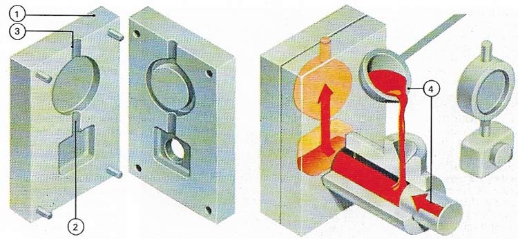
Figure 2. Die casting is a method of making large numbers of castings from non-ferrous metals. Common die castings, such as letter boxes and door knobs, are made from alloys of zinc. Instead of a sand mold (1A), which makes only one casting, a die or permanent mold (1) is used. This is made of cast iron with runners (2) and risers (3) like a sand mold, and it can be opened to get the casting out. For a hollow casting, the metal cores are either part of the die or retractable to release the casting. The metal may be cast by gravity or pressure from a plunger (4).
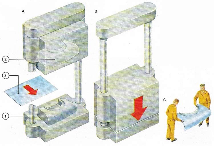
Figure 3. Press tools which consist of a die (1) and a counter die (2) are made of hard steel (A). A piece of sheet metal (3) is put between the two and the press closes on it (B). This method is used for forming sheet metal into various shapes, including simple bends and complex curves. The various sections of body panels of an automobile (C), for example, are generally pressings. Sharp curves may require several successive pressings, each with a tighter curve than the one before, on different machines. The different press operations such as blanking (cutting a piece to the right shape in the flat) or piercing (making holes in it) may be done on different presses or some may be combined, depending on the size and thickness of the material.
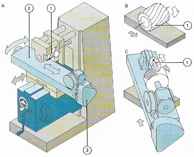
Figure 4. Milling machines cut metal with a rotary cutter (1). The universal mill (A) has a table which can be moved in all 3 planes (2). A workpiece is clamped to the table or to the dividing head. Gears (3) allow the workpiece to be rotated during or between strokes. As well as milling surfaces and grooves, the machine can plane a flat workpiece (B). A cutter can be angled to mill threads. (C) shows the dividing head being used to make a helical cut on a cylindrical workpiece.
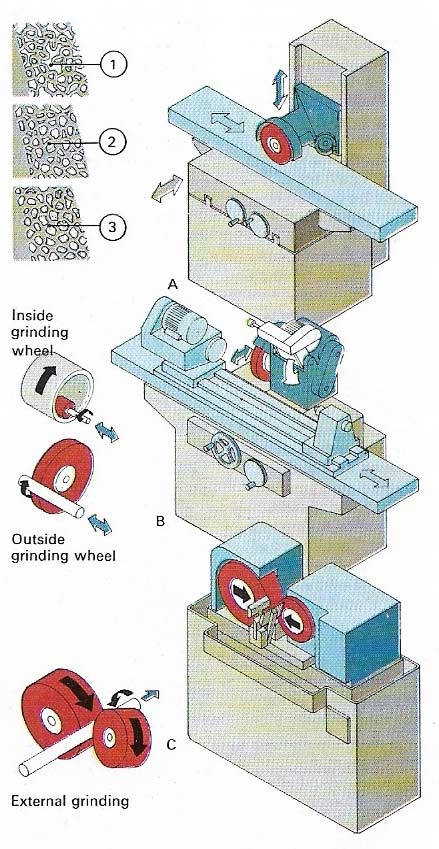
Figure 5. Grinding is used mainly as a finishing operation giving a smooth surface. The grinding wheel consists of hard particles, usually alumina or silicon carbide bonded together with a resin. Three types of grinding machine are shown: the surface (A), universal (B), and centerless grinders (C). (A) smooths plane surfaces, (B) is restricted to internal and external cylinders, and (C) to external cylinders or long bars. Sections 1, 2, 3 are soft, medium, and hard grinding wheels.
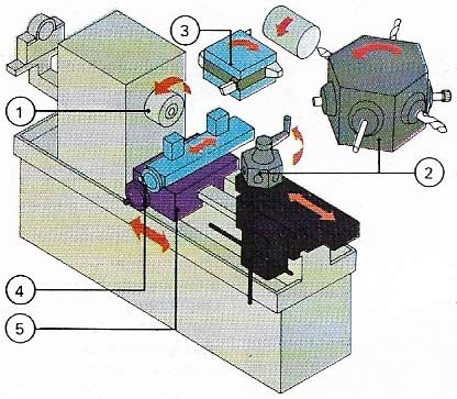
Figure 6. Turret lathes are for repetitive work where large numbers of the same component have to be made from bar or tube fed through the chuck (1). Six tools can be used on the turret (2), and a front tool post (3) on the cross slide (4) of the saddle (5) can carry four more. A rear tool post can also carry tools.
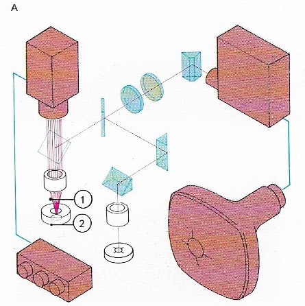
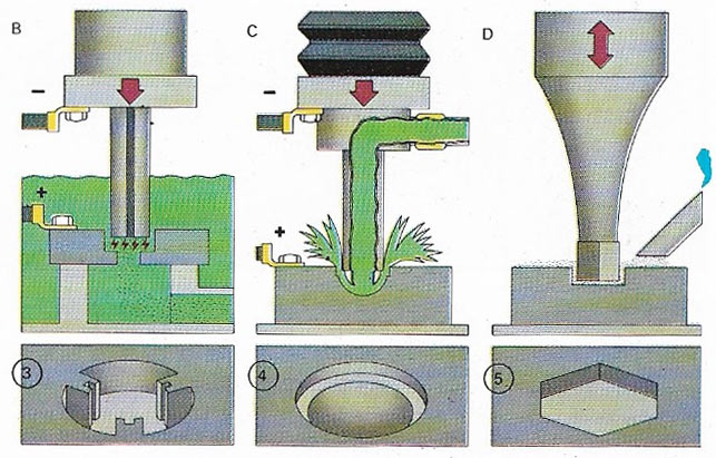
Figure 7. New techniques in metalworking include laser machining (A) in which an intense beam of light (1) cuts hard material (2) such as diamond and tool steel. The image of the work and that of the pattern are combined on a closed- circuit TV display. In spark erosion (B), a high-voltage spark etches away small pieces of a hard material. In electrochemical machining (C), corrosion of metal in salt solution (brine) is speeded up using a high voltage. The hole is cut the same shape as the electrode. Ultrasonic machining (D) uses high-frequency sounds beyond the range of human hearing to vibrate a cutting tool. An abrasive powder then cuts through the workpiece, which could therefore be a non-metal. A cavity is produced which is a mirror image of the tool. Typical shapes produced by these various methods are shown in (3, 4) and (5).
Ever since Hiram of Tyre made the pillars of Solomon's temple in metal, people have continued to work metals for construction mainly by casting and forging. In casting, molten metal is poured into a mold; in forging, the metal – hot or cold – is beaten into shape with a hammer. These are still the two basic metalworking processes.
Casting and forging can be used to produce articles in which accuracy is not of prime importance. But when accuracy in a product is essential, then foundries supply metal in stock forms such as ingots, castings, sheet, bar and tube for subsequent machining to the required shapes.
Casting and forging
Traditional sand casting (Figure 1), such as a sculptor might use, has to be employed for bulky or irregular shapes, especially in iron and steel. Huge solid masses, such as a propeller for a giant tanker, could hardly be made in any other way. Even so, the finished casting needs to be machined or ground to the exact profile and smoothness.
Some small metal parts can be made by the repetitive process of die casting (Fig 2). There are also special items, such as turbine blades for jet engines, which have to be made of metals that stay very strong even when extremely hot and casting is often the only economic way of making them even if they are quite small.
For many other items of all sizes, forging can be the answer. The modern equivalent of the blacksmith's hammer is the giant hydraulic press. Used for large masses of metal, it squeezes white-hot billets under a force of perhaps 50,000 tonnes. For small products die forging is used. The soft, hot "blank" is banged into shape between two precisely shaped dies which come together in perfect register.
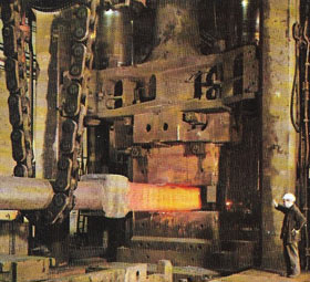 |
| In forging, cast ingots or billets of metal are heated red hot and stamped roughly to shape in powerful hydraulic presses. |
A variation of forging is hot rolling. An ingot or "bloom" is passed, glowing with heat, between pairs of shaped rollers like a giant mangle. It may make dozens of passes, sometimes being reheated, as it grows longer and thinner. Eventually it will become an exact strip, an angle-section bar, a structural girder, a railway rail or, in modern plant, a seamless length of tube. In other modern metalworking techniques basic metal stock, such as bar, rod or tube, is machined to the final required shape.
Using machine tools
Machine tools work with much greater power than a craftsman can exert with his hands. They therefore fashion metal parts faster and at a lower cost. But far more important is the fact that they exert rigid control over the workpiece and are cutting or shaping it all the time. They can go on making the desired number of parts, each identical to the last, so that the machine-made parts are interchangeable. Each conforms exactly to an original drawing showing precise shapes, dimensions and tolerances. The tolerances indicate by how much a dimension can be slightly larger or smaller than the desired value, and are ,measured in micrometers or thousandths of an inch. Without modern machines a craftsman would be hard-pressed to maintain such accuracy and his rate of output would be very low indeed.
Machining a metal involves cutting it with a machine tool such as a milling machine (miller), planer, router or lathe. Millers (Figure 4) hold the work still while rotating cutters pass over it. Planers draw large items past a fixed cutter, whereas a router resembles a drill which mills the surface instead of boring holes. Grinders (Fig 5) use another method of machining, but instead of having cutting tools of very hard metal (or sometimes even diamond) they use wheels with surfaces made up of millions of hard fragments, each of which takes a small cut. Lathes (Figure 6) rotate the workpiece while tools are arranged to cut it.
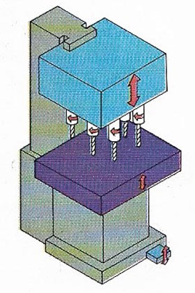 |
| Drilling machines of many different kinds are used in workshops. The multi-spindle model shown is a time-saver in mass production. It can be installed as part of a machining line for a particular component, and tooled to drill all the holes in that the component in one operation. |
Advances in metalworking
Since 1950 many completely new ways of working with metal have been brought from the research library to the production plant. The aircraft industry pioneered chemical milling, in which sheets of any size are etched away in baths of acid or other corrosive chemicals. Portions of sheet can be protected by a surface mask which prevents them from being attacked. The rest can be eaten away in a controlled way, with no scratches or machining marks on the surface. This is important because even the smallest scratch or imperfection can induce metal fatigue.
Electrochemical machining (ECM) (Figure 7) is a variation in which the liquid bath is not corrosive but an electrolyte (carrier of electric current). The workpiece is connected in an electric circuit and then eaten away by a shaped electrode, rather like electroplating in reverse. Another electrical method is spark erosion (8), in which even the hardest parts are gradually shaped by millions of sparks. Yet another, and totally different, electrical method is electromagnetic forming when massive currents are suddenly switched through magnetic coils which slam the workpiece against shaped dies.
In contrast there are other new methods of extreme delicacy used for shaping on a microscopic scale. Ultrasonic machining (Figure 7) is a form of grinding, useful for extremely hard material or non-metals that must be finely shaped. Electron-beam machining uses a concentrated beam of electrons to melt away parts not wanted. Laser machining (Figure 7) does the same with an intense beam of light. Such methods can be used to shape electronic circuits that would easily fit on a pin's head.

