
AC circuits
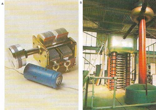
Figure 1. A capacitor or condenser (A) is a component used primarily in alternating current circuits (particularly in electronic applications). The two parallel plates alternately store electrons as the current varies. The capacitor holds the electrons in balance and releases them at the same rate as the supply current, but out of phase with it. Shown here are (top) a variable capacitor consisting of parallel metal plates separated by air gaps, commonly used as the tuning control in a radio set, and an electrolytic capacitor (bottom) consisting of a roll of aluminum foil. In (B) a large industrial capacitor is shown.
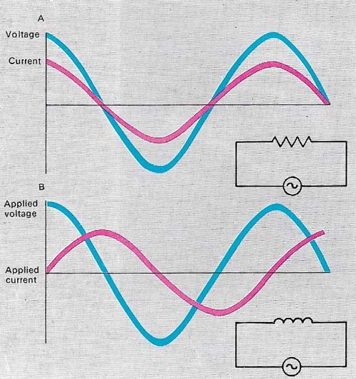
Figure 2. In an AC circuit that has only resistance in it (A), the voltage applied and the current flout are exactly in phase, that is, their maxima, minima and zero points always occur at the same instant; this is true no matter how quickly the voltage fluctuates. With only inductance in the circuit, the voltage and current are out of phase. In an inductive circuit (B), current is said to lag the voltage, or the voltage lead the current. In a capacitive circuit, the reverse applies – the current leads the voltage. The inductor and capacitor (unlike the resistor) store energy and release it out of phase with the input – something like flywheels on steam engines.
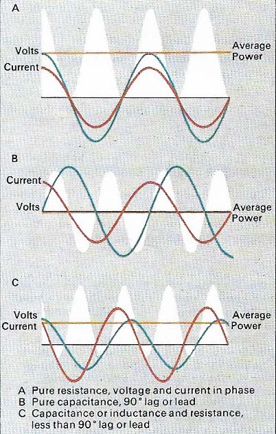
Figure 3. Power in an AC circuit is the instantaneous product of voltage and current averaged over a fixed period. In a resistive circuit (one that has resistance only) the voltage and current are in phase (A) and the power dissipated is given by the formula VI (voltage × current). In a purely capacitive circuit (one that has capacitance only) the current and voltage are 90° out of phase and the circuit returns as much power as it absorbs (B). This also applies to a purely inductive circuit (one that has inductance only). There is, however, always some resistance present; the phase angle ϕ is no longer 90°, and some power is absorbed according to VIcos ϕ (C).
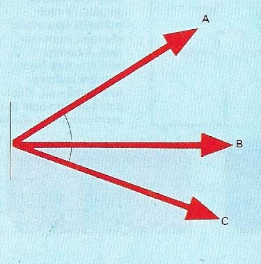
Figure 4. A vector diagram shows the relationship between the three branches of current in a capacitance, resistance, and inductance. Three currents and their phase relationships with the applied voltage are depicted, by convention, by lines whose lengths represent the various values of current (they are vectors): A is said to lead, B to be in phase, and C to lag behind the voltage.
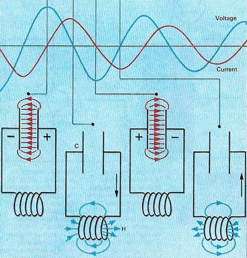
Figure 5. A circuit with inductance (H), resistance, and capacitance (C) may contain some voltages out of phase with the common current. It is possible for those of leading components to cancel out those of lagging components, when the circuit is said to be resonant. Resonant circuits are used in radio sets.
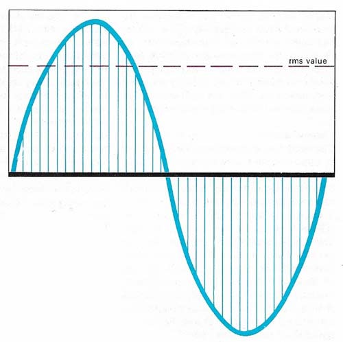
Figure 6. Alternating voltages and currents vary over a cycle from zero to maximum positive, zero and maximum negative. Therefore the average value over the complete cycle is zero and the rms (root means square) or effective value is used as a measure.
The physical processes that take place in electrical circuits carrying alternating current (AC) differ from those in direct current (DC) circuits, reflecting the differences between the two types of electricity. Alternating current regularly reverses its direction, becoming zero before each reversal (100 times a second in European countries and 120 times a second in North America, corresponding to 50 Hz and 60 Hz supply frequencies). With reference to zero, the current is negative and positive alternately. Direct current always flows in the same direction.
Current wave and circuit components
The shape of the "current wave" (the curve representing its change of value with respect to time) can take an infinite variety of forms. For most purposes it is sinusoidal (like a sine wave (Figure 6)).
The number of times the curve repeats the whole alternating cycle in a second is called the frequency and is measured in hertz (Hz) – one cycle per second equals 1 Hz. A sinusoidal voltage (V) applied to a circuit produces a sinusoidal current whose value at any instant in the cycle is equal to V/Z, where Z is called the impedance (which depends on the resistance, capacitance and inductance of the circuit and the supply frequency); Z is measured in ohms (Ω). The equation is analogous to that used to express Ohm's law: the direct current flowing through a conductor is directly proportional to the electromotive force (voltage) that produces it and inversely proportional to the resistance.
The three main types of circuit components are inductors, capacitors and resistors. A resistor behaves in the same way in either an AC or a DC circuit; inductors and capacitors, however, do not. In these devices, currents are out of phase with the applied voltage in parallel circuits (in which there is more than one path for the current) and voltages are out of phase with the current in series circuits (in which the source and output devices are connected by only one path).
Phase lead and lag
A simple analogy to the phase differences in alternating current and voltage is the action of a yo-yo, where the hand from which the spinning mass derives its energy can move in the opposite direction to that of the mass. The current taken by a capacitor is out of phase with the applied voltage; it is zero when the voltage is maximum and vice versa. Sine waves may be represented by rotating vectors (a vector is a quantity that has both magnitude and direction) and on a vector diagram the capacitor current is 90° out of phase with the voltage and is said to be leading.
For a pure inductance the reverse applies – that is, the current lags the voltage by 90°. This can be explained in another way by saying that for a capacitor the voltage lags the current by 90° and for an inductor the voltage leads. With a resistance, the current and voltage are in phase (Figure 2).
In a circuit that has both capacitance and inductance but no resistance, one current leads by 90° and is equal in magnitude to another lagging by 90'. The overall effect is subtractive – they cancel each other out. When this happens the circuit is said to experience current resonance. In effect, the capacitor's current feeds the inductor and vice versa, because each needs the current at different times in the cycle. It is a repeated borrowing and lending action.
In a normal circuit some resistance R is always present. The phase angle between the voltage and current depends on the inductance, capacitance, resistance and frequency. Resonance can still occur when the phase lags and leads cancel out.
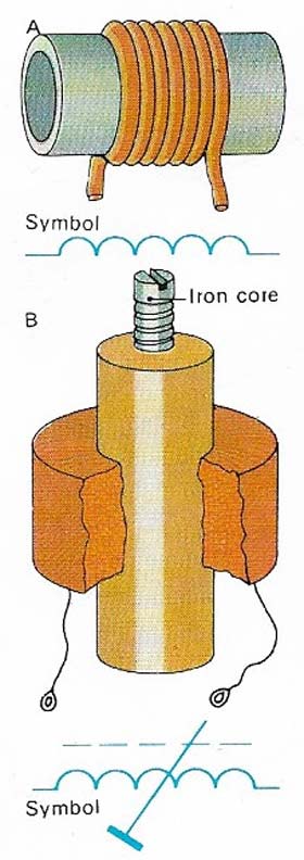 |
| An inductor (A) is a circuit component consisting of a coil of wire. When current flows through a coil a magnetic field is set up whose lines of magnetic flux thread through the coil. Their number and distribution depend on the design of the coil. As the field changes in strength with the changing current, flux lines increase or decrease, cutting the windings of the coil. This is the principle of a generator and an emf (electromotive force) is generated in such a way as to oppose current changes. The effectiveness of an inductor can be changed 'by screwing a threaded iron core into or out of the coil (B). |
The actual value of the current taken by a capacitor or inductor depends on three factors: the voltage, the frequency and the value (size) of the capacitor or inductor. The higher the capacitance the higher the current, but for an inductor the current is smaller as the inductance rises. Current or voltage vectors may be added or subtracted using special mathematics to give a resultant vector. The process is similar to that applied to mechanical vectors. Pulling a barge with ropes at an angle from each side of a canal, for instance, gives a resultant forward motion.
Root mean square values
In an AC circuit the magnitude of the alternating voltage or current is defined as the rms (root mean square, or "effective") value. It is used because the average value is zero, since during any short interval of time the number of half cycles in one direction equals those in the other. The rms value can be derived using simple mathematics and is that quoted in all descriptions of electrical equipment. On an electric iron, a plate reading "230V, 2A" refers to rms values. The voltage and current in this case vary constantly in the form of a sine wave, reaching ±325V and ±2.828A – both 50 times every second.
All electrical appliances that are essentially resistive in structure – such as incandescent lamps, heaters and irons – operate perfectly well in either alternating or direct current circuits (provided they are of the same voltage). But equipment that depends on inductive or capacitive properties, such as some motors, transformers and fluorescent lamps, can operate only with alternating current. Alternating current is preferred for the domestic electricity supply because it can be transmitted efficiently and easily from the power station to the domestic consumer and, is safer when it is switched on and off.

