
air brake
On trains, the air brake is the fail-safe brake patented by George Westinghouse
in 1872, which is released when the engineer allows compressed air to enter
the train air line and applied when the pressure is released. On many trucks
and buses, the air brake is applied, using compressed air, on depressing
the brake pedal.
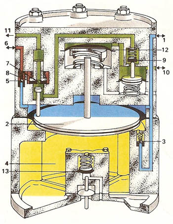
To the right is a simplified diagram of an air brake distributor as used
on railroad rolling stock, based on a design by Westinghouse Brake and Signal
Co. Ltd. Brake distributors are the devices which control the pressure in
the brake cylinders along the train. In order to charge the system, the engineer
allows the normal maximum pressure (about 5 kilograms per square centimeter) to prevail
in the train pipe (1). Air thus enters the area (blue) above the main diaphragm
(2) and flows through a non-return valve (3) into the control chamber (4) –
thus providing a reference pressure. It also flows through a non-return valve
(5) to charge the auxiliary reservoir (6 – red). To apply the brakes,
the engineer allows the pressure in the train pipe to drop (to about 3.4
kg/cm2). The pressure difference across the main diaphragm moves
it upward, closing the exhaust port (7) of the inlet/exhaust valve (8) but
allowing air from the auxiliary reservoir (red) to pass through this valve
and the limiting valve (9) to the brake cylinder (10). To release the brake
again, the engineer again increases the pressure in the train pipe, allowing
the exhaust port on the inlet exhaust valve again to open, and the brake
cylinder is vented to the atmosphere (11 – green), while the auxiliary
reservoir is recharged through the valve (5). Additionally, the upper diaphragm
(12) and limiting valve system allow the brake to be applied partially when
intermediate pressures prevail in the train pipe. Should the train pipe
be broken, or in an emergency brake application, the pressure in the train
pipe drops to atmospheric pressure and the brake is fully applied. When
the vehicle is parked, the control chamber can be vented manually through
the valve (13). As described here there is only one train pipe. Often a two-pipe
system is employed in which there is a separate continuous air supply to
the auxiliary reservoir.

