
bridge
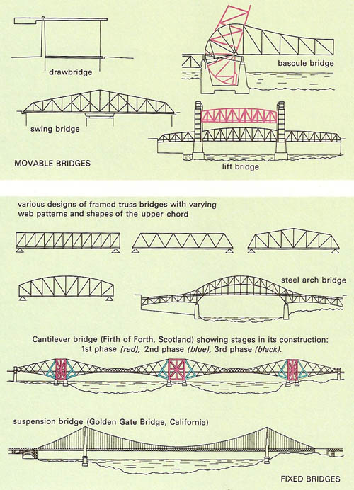
Figure 1. Various types of movable (top) and fixed (bottom) bridges.
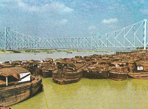
Figure 2. The Howrah Bridge at Kolkata is a cantilever bridge with a span of 453 meters (1,500 feet). The two main piers of this bridge were built hollow with 21 vertical shafts. By digging out the sand at the bottom of these shafts, the piers were made to sink steadily down until they reached impervious clay. The bridge was opened in 1943.
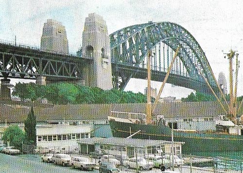
Figure 3. The Sydney Harbour Bridge is a steel arch bridge with a span of 503 meters (1,650 feet) and a height above the water of 52 meters (170 feet). It carried four urban rail lines and six motor lanes and was opened in 1932.
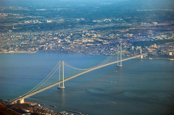
Figure 4. The Akashi Bridge in Kobe, Japan – the world's longest suspension bridge.
A bridge is any device that spans an obstacle and permits traffic of some kind (usually vehicular) across it. Bridges that carry canals are more generally termed aqueducts.
The most primitive form is the beam bridge (or girder bridge), consisting of a rigid beam resting at either end on piers. The span may be increased by use of intermediate piers, possibly bearing more than one beam. A development of this is the truss bridge, a truss being a metal framework specifically designed for greatest strength at those points where the load has greatest moment about the piers. Where piers are impracticable, cantilever bridges may be built; from each side extends a beam (cantilever), firmly anchored at its inshore end. The gap between the two outer ends may be closed by a third beam. Another form of bridge is the arch bridge, essentially an arch built across the gap: a succession of arches supported by intermediate piers may be used for wider gaps. A suspension bridge comprises two towers that carry one or more flexible cables that are firmly anchored at each end. From these is suspended the roadway by means of vertical cables.
Movable bridges take many forms, the most common being the swing bridge, pivoted on a central pier; the bascule (a descendant of the medieval drawbridge), whose cantilevers are pivoted inshore so that they may be swung upward; the vertical-lift bridge, comprising a pair of towers between which runs a beam that may be winched vertically upward; and the less common retractable bridge, whose cantilevers may be run inshore on wheels. The most common temporary bridges are the pontoon, or floating bridge, comprising a number of floating members that support a continuous roadway; and the Bailey bridge.
Two nineteenth-century inventions led to a revolution in bridge building. These were Portland cement and mass-produced steel. Cement is the vital ingredient of concrete, and mass concrete can be used to build piers, abutments (bank supports), and arches of "artificial" stone to any required shape. Well-made concrete is extremely strong in compression (when squeezed) but it has very little strength in tension (when stretched). On the other hand, steel can withstand great tension as well as compression, and can be used for building girders of far greater strength than the wooden trusses of early days. High-tensile steel wire cables will support immense suspension bridges.
Reinforced concrete bridges
These new materials, concrete and steel, can also be used in combination with each other. For example, a concrete structure does not have to be designed so that the material is entirely in compression, because steel rods can be used to carry the tension.
The French engineer Eugene Freyssinet (1879–1962) overcame the remaining weakness of reinforced concrete (the fact that steel in tension stretches, allowing the concrete immediately around the steel to stretch and frequently to crack) by using high-strength tensioned steel wires as the reinforcement. This technique permitted Freyssinet to "pre-stress" concrete (pre-load it in compression), so that it would never be subjected to tension at all. The result was a material so versatile that it could be used to make stronger, lighter and more architecturally satisfactory bridges.
Types of bridge
There are four basic types of bridge: beam, arch, suspension and cantilever (Figure 1). The beam bridge is, in effect, a pair of girders supporting a deck spanning the gap between two piers. Such a beam has to withstand both compression in its upper parts and tension in its lower parts. Where it passes over supports, other forces come into play. A beam may be a hollow box girder or an open frame or truss.
An arch bridge can be designed so that no part of it has to withstand tension. Concrete is therefore well suited to arched bridge design. When reinforced concrete is used, a more elegant and sometimes less costly arch can be designed and most concrete arch bridges are, in fact, reinforced.
A suspension bridge consists, basically, of a deck suspended from two or more cables slung between high towers. The cables, of high-tensile steel wire, can support an immense weight. The towers are in compression and the deck, often consisting of a long slender truss (used as a hollow beam), is supported at frequent intervals along its length.
A cantilever bridge is generally carried by two beams, each supported at one end (Figure 2). Unlike a simple beam supported at both ends, the cantilever must resist tension in its upper half and compression in its lower.
There are also many composite forms of bridges. The bridle-chord bridge is a combination of a long beam (usually a trussed girder) partially supported by steel wires from a tower at one end, or from towers at each end. Most cantilever bridges are designed so that a gap remains between two cantilevered arms that reach out from their abutments; the gap is bridged by a simple beam. "Movable" bridges, like London's famous Tower Bridge, have cantilevered arms or "bascules".
There is more to a bridge than the main span and without proper foundations for the piers or towers the whole structure would fail. Most modern bridges have reinforced concrete foundations, often keyed into bedrock. They may have to be designed to withstand the scouring action of tides, buffeting from pack ice and even mild earthquake tremors. If solid bedrock is too deep to be reached by excavating, foundations can be built on piles driven into the subsoil.
Theoretical limits of bridge spans
A bridge carries two loads. The useful load is the live load of crossing traffic. In addition it must carry its own weight, the dead load. The longer the span of a bridge, the greater its dead load: consequently there is a theoretical span limit for any given material and method of construction. Theoretical limits can be compared with current achievements using modern materials. The longest steel arches in existence are the 575 meters 1,886 feet) Ping'nan Third Bridge in Guangxi, China, which opened in 2020. In fact, the top four longest steel arch spans were are all in China and completed in the 21st century. At number five in the list is the 518 meters (1,652 feet) New River Gorge Bridge in Fayetteville, West Virginia. Among older examples is the 503 meters (1,650 feet) Sydney Harbour Bridge (Figure 3) in Australia, completed in 1932. The theoretical span limit for steel bridges of this type is about 1,000 meters (3,280 feet). In theory engineers have considerable scope here. But the limiting factor is cost, and a long steel arch is not usually the most economical way of bridging a wide gap.
The longest steel cantilever is the 549 meters (1,800 feet) Quebec Bridge in Canada. This was a great achievement considering it was completed in 1918. The theoretical cantilever span limit is about 750 meters (2,460 feet).
The longest reinforced concrete arch yet built is the 445 meters (990 feet) span Beipan River Bridge on the Shanghai-Kunming high-speed railway.
The modern suspension bridge has the greatest span potential. The longest yet built is the Akashi Kaikyö Bridge (Figure 4) with a main span of 1,991 meters (6,532 feet) in Japan. Experienced designers consider a span of 3,000 meters (9,840 feet) to be possible with present-day materials.

