
series circuit
A series circuit is an electrical circuit in which the components are connected end to end, so that the current flows through them all one after the other. The current must move in "series" first going to one component, such as a resistor, then the next. If one of the items in the circuit is broken then no current will flow through the circuit. Old style Christmas tree lights were often wired in series. If one bulb burned out, the whole string of lights went off.
Current in a series circuit
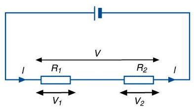
The current flowing through each of the components is the same. This can be written as IT = I1 = I2, where IT is the total current flow, I1 is the current flowing through component 1, and I2 is the current flowing through component 2. To measure the current flow an ammeter is connected to the components in series.
Voltage in a series circuit
As the current flowing through each of the components is the same, the voltage (energy required) to move this current through each of the components is proportional to the resistance of each component. It is the same across each component only if each has the same resistance. If V1 is the voltage across component 1 and V2 is the voltage across component 2, then the total voltage, VT, is given by VT = V1 + V2. The voltage can be measured across each component by connecting a voltmeter in parallel with the component.
See also parallel circuit.

