
synchrotron
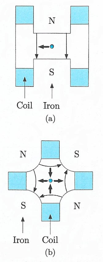
Figure 1. Cross-section of (a) a typical bending (dipole) magnet; (b) a focusing (quadrupole) magnet. The thin arrows indicate field directions; the thick arrows indicate the force on a positive particle traveling into the paper.
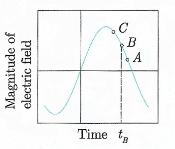
Figure 2. Magnitude of the electric field as a function of time at a fixed point in the rf cavity. Particle B is synchronous with the field and arrives at time tB. Particle A (C) is behind (ahead of) B and receives an increase (decrease) in its rotational frequency. Thus particles oscillate about the equilibrium orbit.
The principle of a synchrotron is analogous to that of a linear accelerator, but the acceleration takes place in a near circular orbit rather than in a straight line. The beam of particles travels in an evacuated tube called the beam pipe and is constrained in a circular or near circular path by an array of dipole magnets called bending magnets (Figure 1(a)). Acceleration is achieved as the beam repeatedly traverses a number of cavities placed in the ring where energy is given to the particles. Since the particles travel in a circular orbit they continuously emit radiation, called in this context synchrotron radiation. The amount of energy radiated per turn by a relativistic particle of mass m and charge q is given by
 |
where β = v/c, v is the particle's velocity, γ = (1 — β2)–½ and ρ is the radius of curvature of the orbit. For relativistic particles (β – 1) of a given energy γmc 2, the energy loss is inversely proportional to the fourth power of the particle's mass. The losses for electrons are thus very severe, and the need to compensate for these by the input of large amounts of rf power limits the energies of electron synchrotrons. This problem can be somewhat reduced by using a very large ring; the highest energy achieved so far was at the LEP facility, located at the CERN laboratory, Geneva. This had a radius of just over 4 kilometers and accelerated electrons and positrons to an energy of approximately 100 gigaelectronvolt (GeV). It operated from 1989 to 2000, when it was decommissioned to make way for the Large Hadron Collider (LHC) discussed below.
The momentum in GeV/c of an orbiting particle assumed to have unit charge is given by p = 0.3Bρ, where B is the magnetic field in tesla and ρ, the radius of curvature, is measured in meters. Because p is increased during acceleration, B must also be steadily increased if ρ is to remain constant, and the final momentum is limited both by the maximum field available and by the size of the ring. With conventional electromagnets, the largest field attainable over an adequate region is about 1.5 tesla, and even with superconducting coils it is only of order 10 tesla. Hence, even for protons, when radiation losses are very small, the radius of the ring must be very large to achieve very high energies. For example, the Tevatron, which operated from 1983 to 2011 at the Fermi National Accelerator Laboratory (FNAL) near Chicago, accelerated protons to an energy of 1 TeV = 103 GeV and had a radius of 1 kilometer.
In the course of its acceleration, a beam may make typically 105 traversals of its orbit before reaching its maximum energy. Consequently stability of the orbit is vital, both to ensure that the particles continue to be accelerated and that they do not strike the sides of the vacuum tube. In practice, the particles are accelerated in bunches. each being synchronised with the rf field. In equilibrium, a particle increases its momentum just enough to keep the radius of curvature constant as the field B is increased during one rotation, and the circulation frequency of the particle is in step with the rf of the field. This is illustrated in Figure 2. Particle B is assumed to be in equilibrium orbit, synchronous with the rf field. Particle A, behind the rf phase, receives a lower momentum increase from the field than particle B. This will reduce the radius of its orbit and (since v ≈ c) increase its rotational frequency relative to particle B. Conversely, a particle C, ahead of the rf phase, receives a greater momentum increase and a decrease in its rotational frequency. With obvious changes, a similar principle is used in linear accelerators.
In practice, the particles remain in the bunch, but their trajectories oscillate about the stable orbits. These oscillations are controlled by a series of focusing magnets, usually of the quadrupole type, which are placed at intervals around the beam and act like optical lenses. A schematic diagram of one of these is shown in Fiureg 1(b). Each focuses the beam in one direction and de-focuses it in the orthogonal direction, so alternate magnets have their field directions reversed to keep the particles in a stable orbit.
In addition to the energy of the beam, one is also concerned to produce a beam of high intensity, so that interactions will be plentiful. The intensity is ultimately limited by de-focusing effects, for example the mutual repulsion of the particles in the beam, and a number of technical problems have to be overcome.

