
transformer
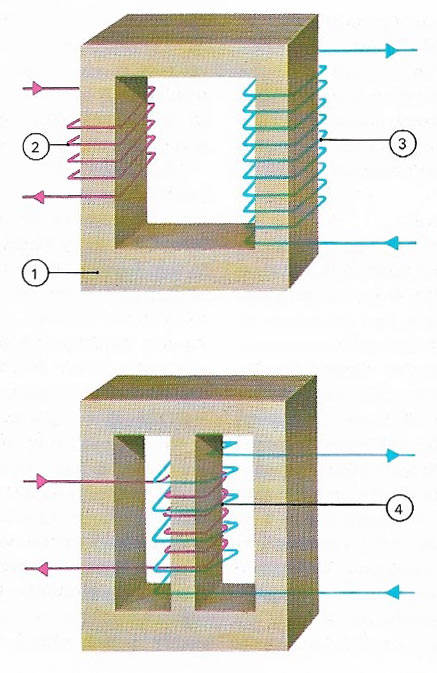
Figure 1. The transformer, a simple and efficient means of raising or lowering AC voltage, consists of three basic elements: an iron core (1), which provides a magnetic link between the primary or input (2) coil and the secondary, output coil (3). The turns ratio between the input and the output determines the ratio between AC voltages 'transformed'; fewer turns on the output side give a proportional decrease in voltage and vice versa, transforming the flow of current. The core may take a number of shapes; sometimes more than two coils are used and sometimes the two coils are wound on each other (4).
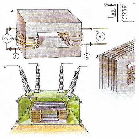
Figure 2. In the transformer (A), the input of primary current (1) causes lines of magnetic flux to form in the iron core, linking it to the output or secondary (2)> As the supply alternates the flux lines collapse and reform in the same pattern, but with different polarities. They induce a voltage in the output coil. The ratio of input to output voltage (V1 to V2) is the ratio of turns on the input and output coils. The iron core is laminated (B) to reduce eddy currents. The high-voltage transformer (C) has its terminals insulated to prevent 'flashover'.
A transformer is a device for altering the voltage of an alternating current (AC) supply. It is used chiefly for converting the high voltage at which power is transmitted over distribution systems to the normal domestic supply voltage, and for obtaining from the latter voltages suitable for electrical and electronic equipment.
The transformer is based on electromagnetic induction: the "primary" voltage applied to a coil wound on a closed loop of a ferromagnetic core creates a strong oscillating magnetic field which in turn induces in a "secondary" coil wound on the same core an AC voltage proportional to the number of turns in the secondary coil. The core is laminated to prevent the flow of eddy currents which would otherwise also be induced by the magnetic field and would waste some of the energy as heat.
Principle of a transformer
Look at the illustration on the right. You will see a light bulb attached to a ring of wires held in a person's hand, and this bulb is lit. Where does the energy come from to light the bulb? Obviously it can't come from a battery or dynamo, because the ring of wires is not attached to anything. The answer is that the magnetic field of the iron bar which stands in the center of the ring of wires induces a current in the wires and so lights the bulb. But why should the iron bar have an electromagnetic field? This is caused by an alternating current flowing through the spiral of wires which have been wound around the lower part of the iron bar.
To use an electrical current in one wire to produce a magnetic field and thus induce a similar current in another wire is an interesting experiment, but it has little practical use. However, by arranging the wires in a particular way it is possible to modify the magnetic field and produce an induced current, or output, which has very different electrical characteristics from the original, or input, current.
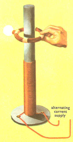 |
| A simple experiment that demonstrates the principle
of the transformer.
|
Building transformers
Transformers made today vary in size from the tiny ones used in the miniaturized electronic equipment of spacecraft to giants that can handle all the electricity needed for a small town. In spite of these great differences in size, however, all transformers are designed according to the principle demonstrated in the experiment with iron bar.
The wires that carry the input current are wound around one side of the core and they are known as the primary windings. The wires in which the output current is induced are wound around the opposite side of the core and are known as the secondary windings. Transformers with more turns in the secondary than in the primary windings are called step-up transformers because they provide an output of higher voltage than their input. Transformers with fewer turns in the secondary than the primary windings are called step-down transformers as their output voltage is lower than their input.
Small transformers are often supported merely on metal frames, and the windings are left uncovered. Others are fitted into small metal or plastic boxes which provide protection against damage. Large transformers are usually housed in oil-filled tanks. The oil absorbs the heat that is generated while the transformer is working and dissipates it through tubes on the outside. In this way the core and windings are kept cool. Some large transformers, however, produce more heat than can be removed conveniently in this way and so they have to be provided with electrically driven pumps which circulate the oil through radiators to keep it cool.

