
hydrofoils and air-cushion vehicles
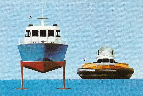
Figure 1. Hydrofoils and air-cushion vehicles are lifted and supported by the expenditure of energy – unlike waterborne ships or land vehicles resting on wheels. A hydrofoil (A) lifts itself to reduce drag, so as to run at high speed and travel smoothly across rough water. A hovercraft (B) does the same, but has the ability to traverse almost any kind of surface, including swamps, mud, river rapids, and ice. The skirt fitted to amphibious hovercraft helps retain the supporting air cushion and lifts the rigid structure higher above the surface.
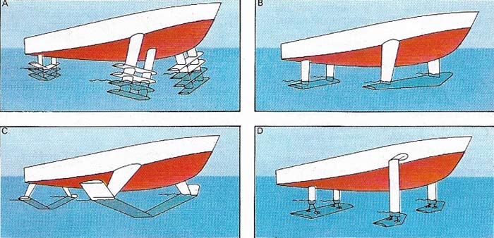
Figure 2. Almost all hydrofoils belong to one of four classes. Ladder foils (A) emerge progressively from the water as speed is increased. Depth-effect foils (B) are suited to shallow water without waves. Surface-piercing foils (C) are the most common form for passenger hydrofoils, while submerged foils (D) are preferred for rough seas. The foils are adjustable and their angle is controlled by an autopilot.
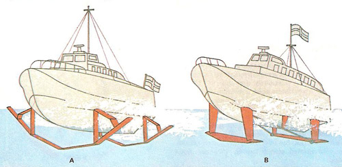
Figure 3. Common hydrofoil configurations (left) surface-piercing foils; (right) fully submerged foils.
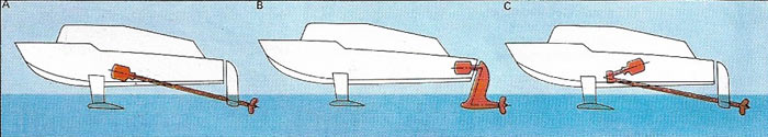
Figure 4. Propulsion poses problems because a hydrofoil's screw is lower than the engine. The sloping drive (A) is simplest but the thrust acts at a sharp angle. The Z drive (B) is best for deeply submerged foils, but requires two sets of bevel gears. The V form (C) is general on surface-piercing foil boats. An alternative is to use the engine to drive a pump, which squirts a water jet out at the stern to provide thrust.
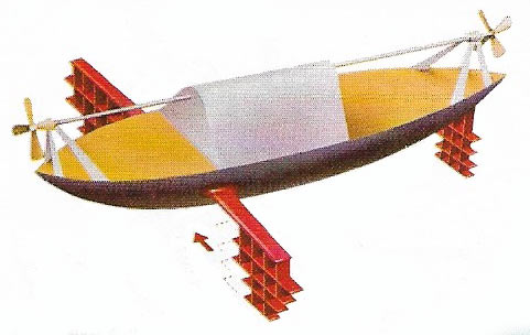
Figure 5. The first full-scale hydrofoil was built in 1906 by Enrico Forlanini (1848-1930). Lifted on three sets of ladder foils and propelled by front and rear screws, it successfully ran at 71 kilometers per hour (44 mph). In 1918 a foil boat built by Alexander Graham Bell (1847–1922) reached 114 kilometers per hour (71 mph). Commercial development of the hydrofoil began in the 1930s.
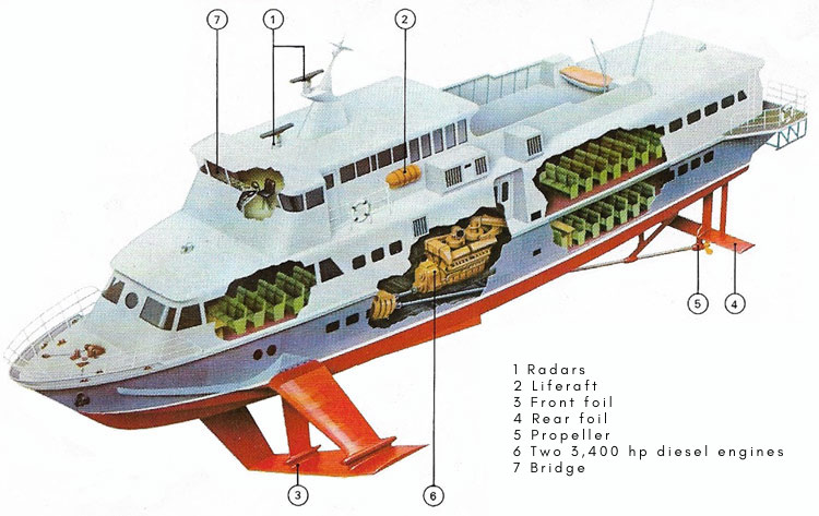
Figure 6. The Swiss surface-piercing hydrofoil known as the PT 150-DC is one of the largest afloat. It is 37.9 meters (124 feet) long overall with a maximum beam of 7.5 meters (25 feet) and can carry 250 passengers at up to 67.5 kilometers per hour (42 mph) for 400 kilometers (248 miles). The vessel has air conditioning and heating which maintains the cabin temperature between 20 and 25°C (68–77°F). In addition to the surface-piercing front foil there is an air-stabilized submerged rear foil. Twin propellers are sited below the rear foil. There are four passenger saloons, two on the main deck and two on the lower, and passengers can be served drinks and refreshments in their seats. The Malmo-Copenhagen ferry uses a PT 150-DC hydrofoil.
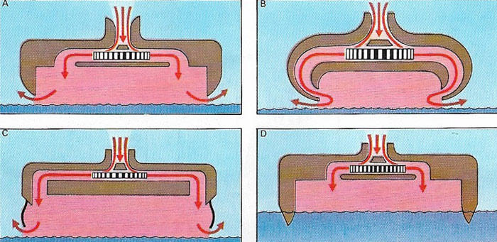
Figure 7. There are four basic types of ACV, each with a central lift fan. The simple "plenum chamber" (A) blows in air which escapes beneath the downturned edges. The peripheral jet (B) blows air inwards from a surrounding slit. With a skirt (C) the rigid body is raised above waves and solid obstructions. ACVs designed solely for use over water have side walls (D), saving lift power but adding extra water drag.
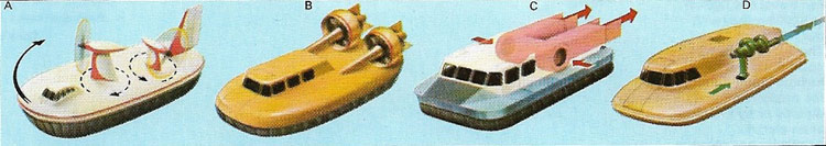
Figure 8. ACV propulsion and steering is often by swivelling propellers (A). To reduce noise and danger, ducted fans (B) may be used, or the propulsive jets , may be provided by the same fans that inflate the cushion (C). Like the fast hydrofoil, the sea-going ACV may be propelled by water jets (D). Unless the propulsion system swivels. deflectors or rudders are needed to control the craft at speed or at rest.
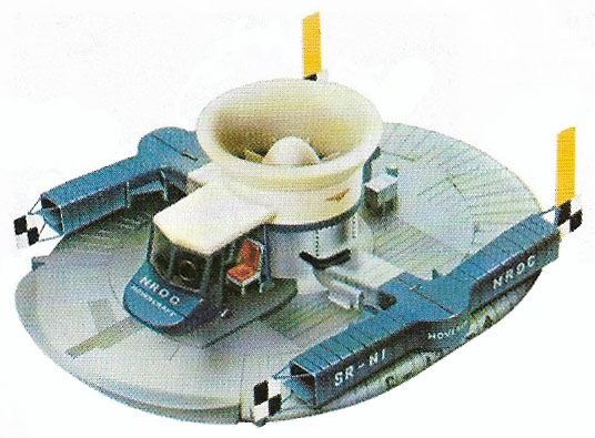
Figure 9. The first commercial hovercraft (A), SR-N1, (1959) was initially powered by a 450 horsepower piston engine driving a fan, which fed the cushion as well as control propulsion ducts on each side. SR-N1 was later fitted with a skirt and a jet engine for high speeds.
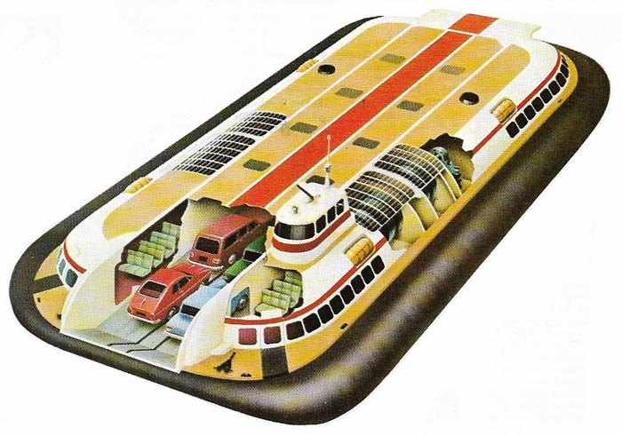
Figure 9. The VT1 was a large commercial ACV built in 1969 by Vosper Thornycroft. Designed to carry 10 cars and 146 passengers, it was propelled by water screws, yet had a skirt and could run out of the water up a slipway for loading. This design combined advantages of high speed with economy and low noise levels. Subsequent civil and military versions of the VT1 were fitted with a new propulsion system, the water screws being replaced by large ducted air propellers.
In common with aircraft and helicopters, hydrofoils and air-cushion vehicles use energy for both upward and forward motion (Figure 1). A hydrofoil is a structure which, when moved rapidly through water, generates lift in exactly the same way and for the same reason as does the airfoil. It is usually mounted beneath a vessel (also called a hydrofoil). Much of a conventional boat's power is spent in overcoming the drag (resistance) of the water; as a hydrofoil vessel builds up speed, it lifts out of the water until only a small portion of it (struts, hydrofoils, and propeller) is in contact with the water. Thus drag is reduced to a minimum. Hydrofoils can exceed 125 kilometers per hour as compared with conventional craft, whose maximum speeds rarely approach 80 kilometers per hour.
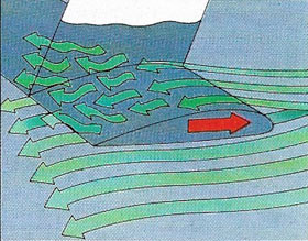 |
| Hydrofoils are sea wings. At speed they generate enough lift to raise the vessel out of the water, thus reducing drag. |
An air-cushion vehicle (ACV) lifts itself in order to become independent of the surface over which it travels, which can be water, snow,marsh, or sand. Today, each type of vehicle has a different use.
Hydrofoils and their uses
The first hydrofoils were built at the beginning of the 20th century. Designers calculated that a sea wing (a lifting plane designed for running through water (Figure 1) could be made much smaller than an air wing capable of generating the same lift force. Early experiment used foils stacked in the form of "ladders" (Figure 2A) so that, as the craft accelerated and lifted, fewer foils remained in the water.
By 1940 the more efficient surface-piercing foil (Figure 2C) had become preferred. In this type of hydrofoil a large foil slopes upon each side of the center line, looking from the front like a V with the tips emerging from the water. These foils provide built-in stability in banked turns or through waves.
Most modern hydrofoils are of this type, although two other designs are also current. Some hydrofoils have depth-effect foils (Fugure 2B), which stabilize automatically an inch or so below the surface of the water. They are ideal for use on shallow draft vessels for inland waterways but are useless in rough sea. For this application, submerged foils (Figure 2D) are the best solution and these are the type used on most high-speed military hydrofoils. Small foils run deep in the water, supporting the vessel on streamlined struts. The angle of the foil can be varied by an autopilot, enabling the craft to run true even in heavy seas.
Most hydrofoils are fairly small, few civil types reaching a150 metric tons and the largest military version being 320 tons. As inshore ferries they can travel at high speeds without damaging river banks or disturbing smaller craft with their wash, and they give a smooth ride across choppy seas. Naval hydrofoils provide maneuverable platforms for guns, missiles, and antisubmarine search and attack systems. At low speeds, a hydrofoil behaves like a conventional ship and floats with its hull in the water. Control remains precise and the craft can ride out storms.
The story of the hovercraft
A hydrofoil is restricted to water and at low speeds needs deep water to float in. By contrast, a hovercraft – the most common kind of air-cushion vehicle (ACV) – is able to go practically anywhere.
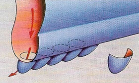
In the nineteenth century, engineers such as John Thornycroft (1843–1928) tried to reduce drag by pumping bubbles out of holes in a ship's hull. Later ACV developments sprang from the experimental work in the 1950s of Christopher Cockerell (1910–1999), who realized that some sort of "curtain" to contain the air cushion under the vehicle was essential to provide sufficient lift within the practical limits imposed by engine size.
Modern ACVs ride on a single bubble or cushion of air blown by fans through slots or jets round the underside of the hull (Gigure 6). The main part of the hull serves as a buoyancy tank, enabling a waterborne ACV to float when the lifting power is switched off. Air pumped by the lift fans raises the ACV on a cushion of slightly pressurized air, which leaks away round the edges at the same rate as it is fed in. The propulsion and lift systems may be driven either by one power plant or by separate units.
Early ACVs had flat undersides and daylight was visible beneath them when they were operating, although clearance was often only a few inches. To improve their performance over waves and other obstacles, later ACVs were fitted with flexible skirts (Figure 7). These skirts contain the cushion of air but pass easily over obstructions. This facility makes them truly amphibious and they can operate equally well in or out of water. Unlike hydrofoils they are not limited in size and large passenger-carrying craft and car ferries are being used. Various types of propulsions and steering systems have been tried (Figure 8), some combining both functions.
 |
| The skirt of an amphibious ACV is made of tough, rubberized fabric to withstand heavy wear. Air inflates the inner and outer walls, escaping through inward facing ducts or "fingers". These inflate the main cushion. They are designed for quick and easy replacement, since they are the parts most likely to be damaged. |
Early optimism about the future of the ACV was not borne out by subsequent development. The craft has not yet shown itself to be completely economical for commercial use, probably because today's vehicles are too small.
Other uses of ACVs
Apart from conventional passenger transport, ACVs have proved their value in the military sphere and the principle of the air cushion has been applied successfully to other modes of transport. The ACV system can be used on a train running over a smooth track, the air cushion reducing friction while propulsion is obtained from ducted fans or linear induction motors. As heavy load carriers ACVs are able to transport machinery weighing 500 tons over surfaces that could not possibly be traversed by wheeled or tracked vehicles. Air-cushion pallets for industrial use are easy to move and reduce strain on floor surfaces. The ACV principle has also been used in the design of hospital beds to lessen the discomfort of patients suffering from burns and for a "land-anywhere" airplane.

