
microphone

Figure 1. Greg Lake at the microphone.
Figure 2. Frequency response curve.
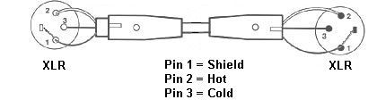
Figure 3. Balanced line diagram.
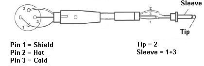
Figure 4. Unbalanced line diagram.
A microphone is a transducer that converts sound waves (acoustic energy) into electrical energy. The first microphones invented were purely mechanical in nature. They worked using a metal diaphragm connected to a needle, which drew a pattern on a metallic foil. When the air pressure changed due to a person's voice, the diaphragm vibrated and moved the needle. The needle then scratched the foil with the vibration pattern. The sound was recreated when the needle was made to run over the foil again. The vibration pattern being followed by the needle makes the diaphragm move and reproduce the sound.
Microphones today work in the same way but the process is carried out electronically. Instead of a scratched foil holding the vibration patterns, the change in air pressure is converted to an electrical signal. The diaphragm can be of any material, such as plastic, paper or aluminum. Diaphragms differ in the way they produce sound, giving rise to different classifications of microphone.
Types of microphone
Carbon microphones
Carbon microphones are among the oldest, simplest, and most used types of microphones even to this day. They work by converting air pressure variations into electrical resistance. The membrane collecting the sound waves presses against a carbon dust material that varies its electrical resistance in the process. By running electric current through the carbon dust, one can obtain an electrical current variation that is amplified and recorded.
Condenser microphones
Condenser microphones rely on the properties of capacitors. The plates of the capacitor are free to move in relation to each other according to the air pressure changes. This generates a variation in the capacity of the device, which can be converted into electric signals.
Dynamic microphones
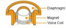
Dynamic microphones are based on the principle of electromagnetic induction. There are two main types. The moving-coil microphone uses a magnet, a coil wrapped with wire, and a diaphragm that sits over the top of both the magnet and the coil. Sound waves cause the diaphragm to move, and in turn, the attached voice coil moves, translating its motion into an electrical signal. The ribbon microphones uses a thin ribbon suspended in a magnetic field. The vibration of the ribbon translates into inductance variations inside the coil generating the magnetic field.
Piezoelectric microphones
Crystal microphones are based on the piezoelectric effect. Piezoelectric materials have the ability of directly converting electric energy into mechanical movement and vice versa. The most common piezoelectric material occurring naturally on Earth is quartz, which is often used to make crystal microphones.
Microphone characteristics
The major differences between microphones are the transducer type and the pickup pattern.
Transducer types
 |
| Dynamic microphone transducer |
 |
| Condenser microphone transducer |
The two basic microphone transducers types are condenser and dynamic.
In a dynamic microphone, a coil of wire is mounted on a diaphragm, which sits inside a magnetic field. When the diaphragm is moved by the sound source the resulting fluctuations in the magnetic field create an electric current that travels from the microphone to the mixer or amplifier. Dynamic microphones are rugged and can handle high sound pressure levels, like those delivered by kick drums, snare drums, and aggressive vocals.
A condenser microphone requires a constant electric charge, provided by a battery or phantom power from the mixer. The condenser diaphragm has less mass, which requires less energy to move, so condenser microphones are more sensitive than dynamic microphones. These microphones are very responsive to high frequencies produced by an acoustic guitars or cymbals on a drum-kit and are used extensively in broadcasting, recording, and sound reinforcement.
Pickup patterns
The pickup pattern is the area around the microphone transducer where the sound is actually "heard" by the microphone. For details, see:
omnidirectional microphone
cardioid microphone
hypercardioid microphone
Impedance
Impedance measures the amount of opposition a device has to an AC current. It is the combined effect of capacitance, inductance, and resistance on a signal. It is measured in ohms and shown with the symbol Ω. All microphones have a rated impedance, which may be written on the microphone itself or on the specification sheet provided with the microphone. There are two general classifications for microphone impedance:
Low impedance: 200–1,000 Ω
High impedance: 10,000–50,000 Ω
Frequency response
The frequency response curve (Figure 2) refers to the way a microphone responds to different frequencies. It is a characteristic of all microphones that some frequencies are exaggerated and others are attenuated. A frequency response that favors higher frequencies means that the resulting audio output will have more treble than the original sound.
Balanced output
The term balanced line means the shield of the cable is connected to ground and the audio signals flow in two conductors which are not connected to ground. In Figure 3 the signal currents are flowing in opposite directions at any given moment in the pair of wires so any electrical noise is common to both wires, and so is effectively cancelled out. Most modern microphones have balanced outputs and this offers real advantages over unbalanced microphones. Balanced lines are much less susceptible to radio frequency interference (RFI) and the pickup of the other electrical generated noise.
With an unbalanced signal, the cancellation effect cannot happen when only one signal wire plus the shield is used. It is possible to wire a low-impedance microphone directly to an unbalanced low-impedance input (Figure 4) but the noise-canceling benefit will be lost. This should not be a problem with cable runs of about 6 meters, but if longer cables are used, a balanced input is preferred.

