capacitor

A capacitor is a component of an electric circuit that has capacitance. A capacitor has at least two metal plates and is used principally in AC (alternating-current) circuits. The various types include parallel-plate capacitors and electrolytic capacitors.
The unit for capacitance is the farad (F), equal to one coulomb per volt. Capacitors normally have very small values and so are often measured in mF (10-3 F), μF (10-6 F) or pF (10-12 F).
Principle of the capacitor
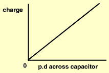
The potential of a charged conductor is affected by the approach of another charged conductor. In particular, its potential is reduced if the approaching conductor is oppositely charged. As the presence of the second, oppositely charged conductor does not alter the charge, Q, on the first conductor, the decrease in potential which it causes must be interpreted as an increase in the capacitance (C = Q/V) of the first conductor. Further, an increase in the dielectric constant of the surrounding medium also results in a lowering of the conductor's potential and, consequently, leads to an increase in its capacitance. Both these approaches to increasing capacitance, bringing near an oppositely-charged conductor and increasing the dielectric constant of the surrounding medium, are commonly used. They make it possible to place upon a conductor, for the same expenditure of energy (= QV/2), a greater charge than would be possible if the conductor were isolated in free space.
Any device for increasing the capacitance of a conductor is called a capacitor. Capacitors normally consist of two plates placed close together and insulated from one another by air or some dielectric material.
In many applications one of the plates is grounded. When a charge is given to the first, "hot" plate, by closing a switch, an equal and opposite charge is attracted, from the ground to the second plate. When the second plate is connected to a point that is at other than ground potential, its charge is again equal and opposite to that of the hot plate, although the amount of charge on each is different, in accordance with the basic capacitor equation Q = CV.
When capacitors are shown in diagrams they are represented as parallel-plate capacitors unless there is some particular reason for indicating their actual geometry.
A dielectric material between the capacitor plates may serve the additional purpose of allowing a much higher potential difference to exist between the plates, without discharging, than would be the case with an air dielectric. With this in mind, reference is often made to the dielectric strength of a material, defined as the field to which the dielectric material must be subjected before a disruptive discharge occurs.


