
electric motor
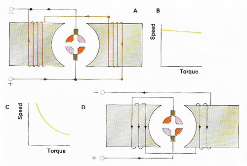
Figure 1. Electric motors are similar in principle to generators. Current supplied to the armature or coil, and to the electromagnetic field, causes the armature to rotate. Connecting the field coils and armature in parallel (A) gives an almost constant speed for any torque (B); connecting them in series (D) produces high torque (C) at low speeds.

Figure 2. Cutaway of a fractional-horsepower single-phase induction motor, as used in many light-industrial applications. This motor has a squirrel-cage rotor which is not wired into the electrical circuit. Since a single-phase motor with a squirrel-cage rotor can start from standstill, a secondary circuit is included in which a capacitor is causes the current in a starting winding to lead the applied voltage, thus enabling rotation to begin. When the rotor reaches a certain speed, a centrifugal switch opens and the capacitor circuit is cut out, leaving the motor to run using only its main winding.
An electric motor is a device for converting electrical energy directly into mechanical energy. Traditional forms of electric motor are based on the force experienced by a current-carrying wire in a magnetic field. Motors can be, and sometimes are, run in reverse as a generator, to produce electrical power from mechanical power.
Simple direct-current motors consist of a magnet or electromagnet (the stator), and a coil (the rotor) which turns when a current is passed through it because of the force between the current and the stator field. So that the force keeps the same sense as the rotor turns, the current to the rotor is supplied via a commutator – a slip-ring broken into two semicircular parts, to each of which one end of the coil is connected, so that the current direction is reversed twice each revolution.
For use with alternating-current supplies, small DC motors are often still suitable, but induction motors are preferred for heavier duty. In the simplest of these, there is no electrical contact with the rotor, which consists of a cylindrical array of copper bars welded to end rings. The stator field, generated by more than one set of coils, is made to rotate at the supply frequency, inducing (see electromagnetic induction) currents in the rotor when (under load) it rotates more slowly, these in turn producing a force accelerating the rotor. Greater control of the motor speed and torque can be obtained in "wound rotor" types in which the currents induced in coils wound on the rotor are controlled by external resistances connected via slip-ring contacts.
In applications such as electric clocks, synchronous motors, which rotate exactly in step with the supply frequency, are used. In these the rotor is usually a permanent magnet dragged round by the rotating stator field, the induction-motor principle being used to start the motor.
The above designs can all be opened out to form linear motors producing a lateral rather than rotational drive. The induction type is the most suitable, a plate analogous to the rotor being driven with respect to a stator generating a laterally moving field. Such motors have a wide range of possible applications, from operating sliding doors to driving trains, being much more robust than rotational drive systems, and offering no resistance to manual operation in the event of power cuts. A form of DC linear motor can be used to pump conducting liquids such as molten metals, the force being generated between a current passed through the liquid and a static magnetic field around it.
Components and operation of an electric motor
The two essential elements of both an electric and a generator are the field and the armature. The field is a magnetic field, which may be derived from permanent magnets or electromagnets. The former are cheaper but the latter are more convenient because with an electrically energized field it is easy to increase or decrease their strength. It is, however, a convenience gained only at the expense of having to provide the coils for the electromagnets that form the field (field 'windings') and to do all the work that goes into insulating and installing them.
How the armature works
The armature is also a winding but it is arranged differently from the field. It is essentially a conductor (or conductors) arranged to cut the field's magnetic lines of flux at right-angles. The armature conductors may be wound onto a cylinder that rotates in a field. Or they may be fixed to the inner walls of a cylinder, within which the field windings rotate. The static part of the machine is called the stator and the revolving part the rotor. Both the field and the armature may be on either the stator or the rotor.
By a basic principle of electromagnetism, a voltage is induced in a conductor that moves in a magnetic field and a conductor in a magnetic field experiences a force and tends to move when a current flows in it.
To make the best use of this basic effect, the magnetic and and electrical elements in electrical machines (the field and the armature) have to interact in the most efficient manner possible. The armature is generally wound on an iron core which concentrates the maximum number of magnetic flux lines. The field coils are also wound on iron cores, to produce the maximum flux for a given current. The iron for both the field and the armature is sometimes laminated – that is, made up of slices (Fig 1). This prevents the currents from circulating and eddying in the iron itself and generating wasted heat, as a result of changing magnetic flux in the machine.
The armature must be supplied with current (through rotating contacts) if it is the rotor in a motor and there must be a way of taking current from it if it is a generator. The same applies to the field if it is electrically energized. The rotating contact arrangement can be either a set of slip-rings or a commutator (3). These rotate under fixed contacts, called bushes, made of carbon and held in place by springs. From time to time the bushes have to be replaced when the carbon wears away.
Varying the field
The armature and field windings of a motor are supplied with current and, by using a resistor in the field circuit, it is possible to vary the field strength. Weakening it causes the motor to revolve faster – provided the armature current is constant – but with less torque (turning force), and vice versa. In a generator driven at constant speed, strengthening the field increases the voltage output; weakening the field decreases it.
The motors and generators described so far are generally suitable for either AC (alternating current) or for DC (direct current) supplies. However, induction motors can be used only with AC supplies. The armature is the rotor and can be wound or made in the form of a 'squirrel cage'). The flux from the stator field is changing and induces a voltage in the cage. This causes a current to flow which interacts with the stator field to produce torque. No slip-rings are necessary.
The simplest field consists of two coils. As one becomes a north magnetic pole, the other becomes south, unlike DC machines whose field polarities are constant. The rotor experiences a pulsating and reversing field, but not one that appears to rotate; without a starting force the armature will not rotate either. Given a push in either a direction, it begins to follow the field as it alternates.
Some induction motors have a wound rotor and slip-rings may be used. The purpose of the rings is not supply current to the armature but to alter its characteristics with the use of external resistances.

