
generator

Figure 1. A practical generator. In this diagram the iron core that fills the space between the axle and the rotating coils has been removed for clarity. The magnetic field is provided by the two electromagnet coils ('field windings') which also have iron cores.
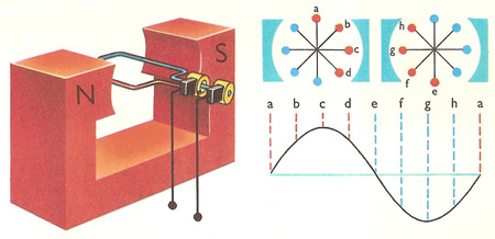
Figure 2. A simple generator. On the right the coil is seen from the end making one complete revolution. The size of the current in each of the eight stages varies as shown by the curve. At 'e' (coil vertical) the current reverses.
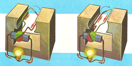
Figure 3. A generator can be made to give a 'one-way' or direct current by connecting the ends of the coil to the two halves of a split-ring or commutator. This device neatly puts whatever is the 'outgoing' end of the coil onto the same brush at the moment the coil comes up to the vertical and reverses the flow. In the first of the diagrams above, the red side of the coil is moving downward and the current produced in it flows out of the coil into the right hand brush. In the second diagram the red side of the coil is moving upward and now the current produced in it flows into the coil. But by this time the red side of the coil is connected to the left hand brush. So the current still flows out of the right hand brush, the rough the lamp and re-enters the generator at the left hand brush as it did in the previous diagram.
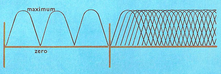
Figure 4. Although the commutator ensures that current always flows in the same direction, it does not prevent the current from falling to zero each time the coil reaches the vertical position. No current is produced when the coil is vertical because it moves along the lines of force instead of cutting across them. With a number of coils it is possible to have the current in one reaching a maximum when the current in another is zero. The commutator in that case consists of several pairs of segments arranged around the axle instead of the two halves of the split ring. The segments are insulated from each other, and the ends of each coil are connected to opposite segments.
An electrical generator is a device for converting mechanical energy into electrical energy. The source of the mechanical energy may be a simple hand crank, an internal combustion engine, or a steam, gas, or water turbine.
History of generators
Generators originated with the discovery of induction by Michael Faraday in 1831; the considerable advantages of electromagnets over permanent magnets were first exploited by E. W. von Siemens in 1866.
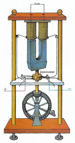 |
The generator shown above was devised in 1883 by the Frenchman Hippolyte Pixii. It consisted of a horseshoe magnet set on end between two coils. The magnet was rotated through a gear system driven by a hand crank. As the magnet rotated, an alternating voltage was induced in the coils. A commutator, added later, enabled positive voltage to be picked off one side, and negative off the other, to produce direct current.
Principle of the generator
Traditional forms are based on inducing electric fields by changing the magnetic field lines through a circuit (see electromagnetic induction). All generators can be, and sometimes are, run in reverse as electric motors.
The simplest generator consists of a permanent magnet (the rotor) spun inside a coil of wire (the stator); the magnetic field is thus reversed twice each revolution, and an AC voltage is generated at the frequency of rotation (see also magneto). Equivalent to this is rotating a coil of wire between the poles of a permanent magnet (Fig 2).
In practical designs (see top illustration), the rotor is usually an electromagnet driven by a direct current obtained by rectification of a part of the voltage generated, and passed to the rotor through a pair of carbon brush/slip ring contacts (Fig 3). The use of three sets of stator coils 120° apart allows generation of a three-phase supply (see also armature).
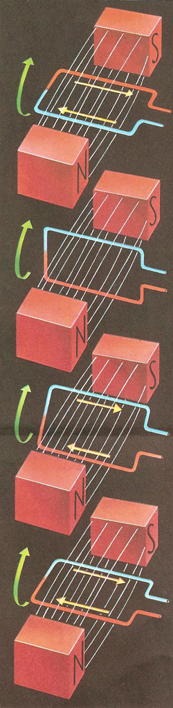 |
| The top picture shows a single coil of wire placed
in a magnetic field. As the coil is turned it cuts across the lines
of force and (if it forms part of a complete circuit) a current is
produced. When the coil is in the position shown in the second picture
it is moving along the lines of force without cutting them. No current
is produced here. In the last two pictures the red side of the coil
again cuts lines of force but this time it is moving upward, so the
direction of current is reversed.
|
Direct current generation
A generator that produces direct current is also known as a dynamo. Simple DC generators consist of a coil rotating in the field of a permanent magnet: the voltage induced in the coil alternates at the frequency of rotation, but it is collected through a commutator – a split-ring broken into two two semicircular parts, to each of which one end of the coil is connected, so that the connection between the coil and the brushes is reversed twice each revolution – resulting in a rapidly pulsating direct voltage. A steadier voltage can be achieved through the use of multiple coil/commutator arrangements, and except in very small generators, the permanent magnet is again replaced by an electromagnet driven by part of the generated voltage.
Large-scale generation
For large-scale generation, the mechanical power is usually derived from steam turbines, or from dam-fed water turbines, and the process is only moderately efficient. The magnetohydrodynamic generator avoids this step and has no moving parts either. A hot conducting fluid (treated coal gas, or reactor-heated liquid) passes through the field of an electromagnet, so that the charges are forced in opposite directions producing a DC voltage. In another device, the electrogasdynamic generator, the voltage is produced by by using a high speed gas stream to pump charge from an electric discharge, against the electric field, to a collector.

