
thermocouple

Figure 1. Thermocouples are used to measure temperature. When a temperature difference exists between the junctions of two dissimilar electrical conductors, a potential difference is created. This causes a current to flow round the circuit. A meter is included to indicate the current (flow of electrons) and it may be calibrated to read in a convenient temperature scale.
A) Both junctions are in thermal equilibrium and no current flows through the meter
B) A temperature difference causes current to flow through meter
1) "hot junction"
2) "cold junction"
3) bismuth
4) copper
5) electron flow.
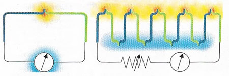
Figure 2. In a thermocouple (left) a temperature difference between he two junctions of a circuit, made of two dissimilar metals, will produce a current, indicated by a meter., which is proportional to the temperature difference. In a thermopile (right), several thermocouples are connected in series to increase the voltage of the circuit.
A thermocouple is a device for measuring temperature that uses two wires of unlike metals, such as platinum and bismuth, or semiconducting rods, which are welded together at their ends to form a junction (Figure 1). The principle behind the thermocouple is known as the Seebeck effect. When a conductor is placed in a temperature gradient, electrons diffuse along the gradient and an electromotive force (emf) is generated. The magnitude of the emf depends on the material and its physical condition. To measure the generated thermal emf, the circuit must be completed using a second different conductor. This is joined to the first conductor at the point of measurement and passes through the same temperature gradient. The thermocouple emf is then the difference between the emfs generated in the two conductors.
In practice, thermocouples have two junctions. One of these is held at the temperature, t1, to be measured, for example in a furnace. The second reference junction is held at temperature t2 which is usually the melting point of pure ice. This can be done with real melting ice or electronically, but with some loss of accuracy. The difference in the emfs generated by the two conductors is then given by:
![]()
where E is the net emf generated and Sa and Sb are the Seebeck coefficients of conductors a and b.
Many different thermocouple combinations have been used, but only eight are standardized in IEC 584-1. These include three noble metal thermocouples using platinum and platinum-rhodium alloys, widely used for temperature measurement up to 1,600°C. The remaining five mainly use nickel-based alloys (see constantan), which are cheaper and more suitable for industrial use up to about 1,200°C. Other refractory alloys can be used up to and beyond 2,000°C.
The simplicity, ruggedness, low cost, small size and wide temperature range of thermocouples make them the most common type of temperature sensor in industrial use.
Thermopile
A thermopile is a device used to measure radiant heat, consisting of several thermocouples connected together in series (Figure 2). Alternate junctions are blackened for absorbing radiant heat, the other junctions are shielded from radiation. The electromotive force generated by the temperature difference between the junctions can be measured. From this the temperature of the blackened junctions can be calculated, and thus the intensity of the radiation measured.

