
helicopter
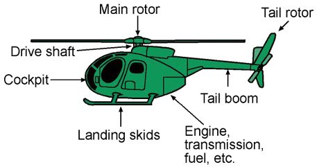
Main components of a helicopter components.
Main components of a helicopter components.
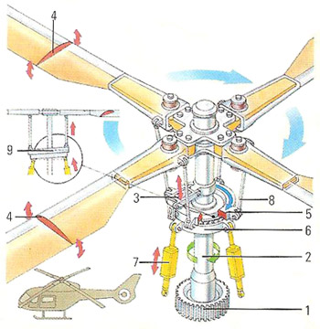
A helicopter rotor head transfers the power of the engines to the rotor blades via gears (1) and the rotor shaft (2). The swish plate controls the tilt of the rotor (3) and also the pitch of the blades (4). The upper (5) and lower (6) swish plates are controlled by hydraulic cylinders (7) attached to the lower plate. The upper plate is connected to the rotor blades by control rods (8). The pitch of the blades controls the amount of lift generated while the attitude of the whole rotor controls how the helicopter moves horizontally. If the rear of the swish plate is raised (9) the rotor dips toward the nose of the helicopter causing it to travel forward.

The combination of a hingeless rotor hub and advanced composite blades of the Westland Lynx (UK) allows a full range of aerobatic maneuvering and was critical in allowing the type to set the absolute speed record of helicopters (400km/h).
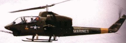
The Bell AH-1 is an example of a semi-rigid rotor system.
The main rotor and tail rotor configuration is used on an Aérospatiale/Westland Lynx.
The Kaman HH-43 uses two intermeshing rotors.
A coaxial rotor is found on the Kamov Ka-25.
The Mil Mi-12 (V-12) uses side-by-side tandem rotors.
Tandem rotors (fore and aft) are found on the Boeing Vertol CH-47 Chinook.
A helicopter is an aircraft that can take off and land vertically through use of spinning rotors. Also called a rotary aircraft, a helicopter can hover and rotate in the air and can move sideways and backwards while aloft. It can change direction very quickly and can stop moving completely and begin hovering.
A helicopter flies by means of the thrust that is created by the rotation of the blades of a main rotor that is mounted on a shaft above the fuselage, or body, of the aircraft. As the blades rotate, an airflow is created over them, resulting in lift. This raises the helicopter. A pilot maneuvers the helicopter by changing the pitch, or angle, of the rotor blades as they move through the air.
An engine is used to create the force needed to lift the aircraft and its passengers and cargo. Reciprocating gasoline and gas turbine engines are the most common types used on helicopters.
All helicopters need a way to counteract the torque produced by the main rotor. If this were not done, the rotor would turn in one direction, and the fuselage would turn in the opposite direction. Usually, a small tail rotor is used to produce a sideways thrust that prevents the fuselage from rotating. By increasing or decreasing the thrust produced by the tail rotor, the pilot can steer the helicopter to the left or right. Another way to counteract thrust is with two main rotors that turn in opposite, or counter-rotating, directions. Each rotor cancels the torque produced by the other. No tail rotor is needed in this type of helicopter.
History of the helicopter
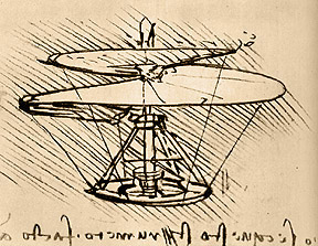
Leonardo da Vinci sketched a helicopter design sometime around 1500. It was essentially a horizontal propeller, powered by a spring mechanism. The vertically-mounted propeller on an ordinary airplane is shaped so that it pushes air backwards as it rotates. By the third of Newton's laws of motions, this backward push produces an equal pull, or reaction, in the opposite direction. Since Leonardo's propeller was mounted vertically, it would push the air downwards and react by tending to pull itself upwards.
It is not known whether Leonardo actually made and flew the helicopter he designed. His drawings and ideas were lost until the 18th century. At that the first toy helicopters came to Europe from China. Their propeller blades or rotors were made of feathers, and the toy was powered by a twisted cord.
So the basic principle of helicopter operation was known and, once a suitable means of powering the rotor had been developed, it seemed to be a fairly simple step to make an actual hovering machine. The rotors were almost flat, light blades, and could be made to slope so that as they rotated they bit the air and pushed it down. The angle at which they slope is called the pitch, and the greater the pitch, the more air the blades push down, and the greater the upward thrust. Similarly, if the blades rotate more rapidly, they will bite more air in a given time, and the thrust will be larger.
In 1907 the Breguet brothers, Louis and Jacques, built a helicopter which could rise four or five feet into the air, but which proved virtually impossible to control.
The trouble was that the helicopter was unstable. As the rotors twist round in one direction, the helicopter tends to twist in the opposite direction. This is yet another consequence o Newton's third law. Something must be done to stop the helicopter from rotating.
If the helicopter were moving forwards it could be stabilized, like an airplane, with fins and rudders. (These make a large air resistance to rotary movement.) But if the helicopter is hovering, fins and rudder are ineffective. The early helicopters were not built to move forwards. It was as much as they could do to get off the ground and stay airborne for a few minutes.
To make the helicopter hover properly, it was obvious that the tendency to twist in one direction could be compensated only by making the helicopter try to twist in the opposite direction. The two twists would cancel each other, and the helicopter would stay straight. The first idea was to have two rotors rotating in opposite directions (counter- or contra-rotating). The twist resulting from one rotor would be balanced by the twist resulting from the other.
Some present-day helicopters use two counter-rotating rotors, but the majority of smaller helicopters use the balancing method invented by Igor Sikorsky (1889–1972). He compensated the twist of the large rotor with a small, sideways-facing rotor mounted near the tail.
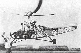 |
| The VS-300, built by Igor Sikorsky, was the first practical helicopter. It first flew in about 1939, but went through many modifications before being perfected. At one stage it could fly in every direction except forward. These problems were overcome by 1941 and production models were tested in World War II. Its single main rotor and small tail rotor became the predominant helicopter design. |
Controlling the helicopter
As soon as the helicopter starts to move forwards another instability sets in. It tends to roll sideways. This stems from the fact that blades moving forwards are moving faster, relative to the air, than those moving backwards. The more air a blade bites, the greater its lifting effect. Blades that are moving forwards bite more air than those moving backward (this is in addition to the changes imposed by cyclic pitch). So since one side is pushed more than the other there is an extra force trying to push the helicopter sideways. It is corrected by spring-hinging the blades at their roots. As a blade sweeps forward, it flexes upwards, thus reducing the amount of air it bites.
The pilot controls the helicopter by using rudder pedals, which turn the helicopter to the right or left, a cyclic pitch stick that tilts that helicopter forward, backward, or sideways, and a collective pitch stick that allows the helicopter to climb and descend vertically.
Rotor systems
A helicopter rotor system is the unit that is composed of a hub and the
blades attached to it. Each rotor is considered a separate system, and a
helicopter may have more than one main rotor.
There are three primary types of rotor systems: articulated, semi-rigid,
and hingeless.
The articulated rotor system first appeared on the autogyros of the 1920s and is the oldest and most widely used type of rotor system. The rotor blades in this type of system can move in three ways as it turns around the rotor hub and each blade can move independently of the others. They can move up and down (flapping), back and forth in the horizontal plane, and can change in the pitch angle (the tilt of the blade).
The hingeless rotor system functions much as the articulated system does, but uses elastomeric bearings and composite flextures to allow for flapping and lead-lag movements of the blades in place of conventional hinges. Its advantages are improved control response with less lag and substantial improvements in vibration control. It does not have the risk of ground-resonance associated with the articulated type, but it is considerably more expensive.
In the semi-rigid rotor system, the blades are attached rigidly to the hub but the hub itself can tilt in any direction about the top of the mast. This system generally appears on helicopters with two rotor blades. These systems resemble a seesaw – when one blade is pushed down, the opposite one rises.
Rotor configurations
The rotors on a helicopter can be configured in several ways. The most common configuration is the combination of one main rotor and one tail rotor. The tail rotor compensates for the torque that is produced by the main rotor. The tail rotor also controls the helicopter along the vertical axis during hover flight.
The tandem rotor (or twin-rotor) configuration is used mainly with large helicopters. Because of the opposite rotation of the rotors, the torque of each single rotor is neutralized. The construction of the control system is much more complicated compared to a helicopter with a tail rotor. The arrangement of two rotors side by side was never very popular. This design was used for the largest helicopter ever built – the Mil Mi-12. The Piasecki helicopters also use tandem rotors – one toward the front of the helicopter and one at its rear.
The twin-rotor synchropter is a system with two rotors that mesh into each other, much like a gearwheel. Like the tandem rotor, this configuration doesn't need a tail rotor because the torque is compensated for by the opposite rotation of the rotors. This system was developed during the early days of helicopter flying but fell into disuse.
Today, this kind of rotor arrangement has been rediscovered and is used with the Kaman K-MAX, a single seat helicopter mainly used for external load transportation.
The last configuration is the coaxial rotor. One rotor is located on top of the other. The two rotors turn in opposite directions. Depending on which rotor produces more lift, the helicopter will turn to the left or right, because of the torque. Helicopters with this configuration cannot reach a high cruising speed because the drag is too large. Only after the development of the rigid rotor was it possible to build the two rotors closer together and reduce the drag considerably. This configuration has been chosen mainly by Russian Kamov helicopters.

