
Jodrell Bank
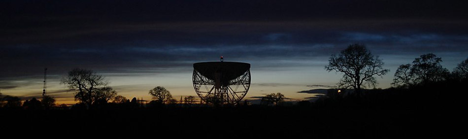
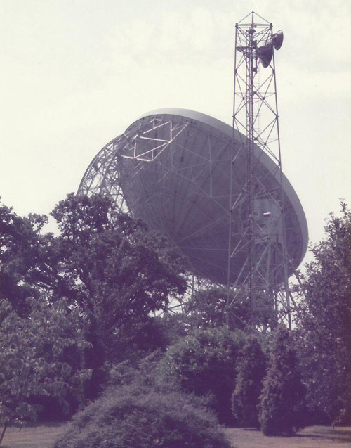
The Lovell Telescope.
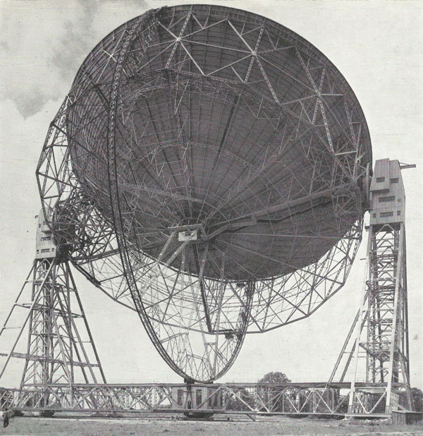
Mark I telescope a few years after its completion.
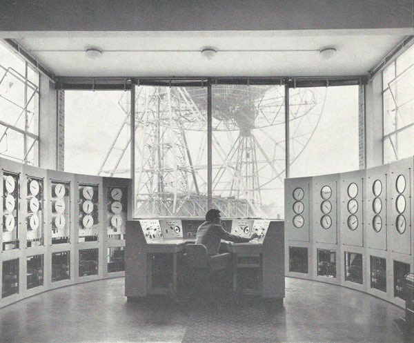
Control room of the Mark I telescope as it originally looked.
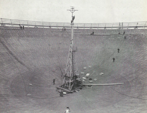
The bowl of the Mark I telescope under construction.
Mark IA (left) and Mark II (right) telescopes.
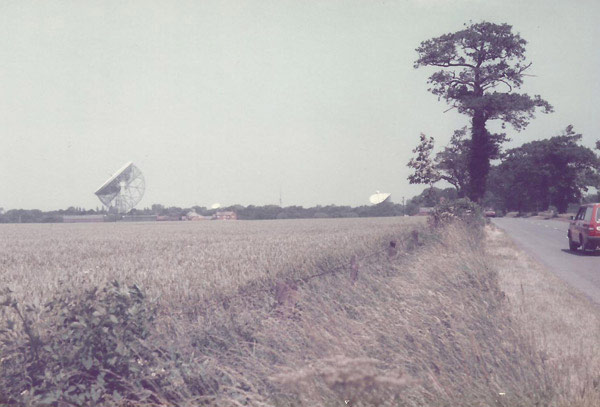
The Lovell Telescope, as it is now known, from the nearby arboretum.
Jodrell Bank is the radio astronomy observatory of the University of Manchester, located near Macclesfield, Cheshire, England. Now known as the Jodrell Bank Center for Astrophysics, it is home to the 76-meter (250-foot) Lovell Telescope (formerly known as the Mark IA and, before that, the Mark I), completed in 1957 under the direction of Bernard Lovell, the first director of the Observatory; this instrument was the first giant steerable radio telescope in the world and is still the third largest of its type.
Jodrell Bank is the operations center for the MERLIN (Multi-element Radio-linked Interferometer Network), a dedicated network of radio telescopes in the United Kingdom for long-baseline interferometry with separations of up to 217 kilometers. It is also the headquarters of the Square Kilometre Array, which, when complete, will be the world's largest radio telescope.
Mark I Telescope
The Mark I, a steerable focal-plane paraboloid radio reflector, could originally receive and transmit radio signals varying in wavelength from about 20 centimeters to 20 meters. Its motion is altazimuth (that is, it can move freely in both horizontal and vertical rotation). Among the engineering challenges to be overcome were that the entire structure, with over an acre of wind-catching bowl, must be steady in storms. It must withstand accumulations of snow and ice, and rain must drain safely and without nuisance from the bowl in any position. It must be accurate in the hottest summer and the coldest winter, and the bowl when pointing at the sun must neither absorb so much heat as to distort the steelwork significantly nor reflect so much heat as to melt the antenna at the focus. It must move smoothly and exactly – usually creeping even less perceptibly than the hour-hand of a watch – so that it can aim constantly at a given point in space regardless of Earth's rotation and orbit, or can scan continuously to and fro over a given portion of the sky, or can follow the track of the Moon, the planets, or an artificial satellite: and all of these movements must be completely automatic.
Foundations
Owing to the irregular sub-soil at Jodrell Bank the ground on which the telescope stands is piled to depths varying from 37 to 90 feet. Some 10,000 tons of reinforced concrete were used in the foundations: these comprise (in addition to the piles) a central thrust block carrying the ball and roller bearing pivot which is the main locating point of the telescope, and a ring carrying the double circular rail track on which the telescope rotates.
Supporting structure
The telescope is built entirely of steel, which was chosen in preference to lighter alloys for four main reasons. First, steel has the greatest strength per unit of cost; secondly, its low coefficient of expansion maintains sufficient accuracy of shape in extreme temperatures; thirdly, its high modulus of elasticity is important in view of the large variations of stress imposed by the telescope's movements; fourthly, its weight (the steerable part of the telescope weights over 2,000 tons) gives stability to the whole structure.
The structure supporting the reflector consists essentially of a horizontal lattice girder with a triangulated lattice tower 185 feet high at each end: the reflector is carried on trunnions at the tower tops, and the entire assembly rotates about the central pivot.
Each tower is mounted on six roller-bogies, four at the corners of the tower base and two at its center. The corner bogies carry part of the weight and act as wind-braces; the center bogies are driven by electric motors to rotate the telescope. The bogies run on a double circular rail track of 17 feet gauge and 352 feet outer diameter.
In order to ensure smooth motion and minimum friction the rail track was laid to a tolerance of only 1/16 inch in line and level, the roller axles of the bogies are radial to the circular track, and the rollers are imperceptibly tapered so that the apexes of their truncated cones coincide with the central pivot.
Reflector bowl
The following, again, refers to the original Mark I bowl and not to any modifications or upgrades that have been made since.
The bowl is a paraboloid of 250 feet diameter, made of welded steel plates and carried in a lattice steel cradle.
At the center of the bowl is a lattice steel tower 55 feet high, and mounted at the top of this tower at a height of 62½ feet (the focus of the paraboloid) is the antenna to which are concentrated the radio waves received and reflected by the bowl.
The bowl and cradle assembly, weighing about 800 tons, is carried by two great roller bearings in the trunnions at the summits of the two towers. The whole assembly is rotated in elevation by electric motors and reduction gears which drive pinions and internal tooth circular gear tracks of 25 feet diameter; the pinions and racks were taken from the gun turrets of two dismantled Royal Navy battleships.
Suspended beneath the center of the bowl just below the base of the antenna tower is the primary laboratory containing part of the main amplification system for incoming radio signals. This laboratory is a small cabin reached by catwalks from other laboratories at the tower tops; it is pivoted to hang on an even keel irrespective of the position of the bowl and is damped to prevent swaying in wind.
The entire bowl and cradle assembly is damped against swaying, flutter and vibration by a great circular stabilizing girder or 'bicycle wheel', whose center lies on the axis of rotation of the bowl. The periphery of this girder bears on a set of pneumatic tires mounted on wheels with controllable hydraulic braking mechanism.
How the telescope moves
The supporting structure carrying the reflector can make one full rotation in azimuth in 18 minutes, at which speed the outer roller-bogies move at about ¾ mph. The reflector can be tilted through one full rotation in elevation in 15 minutes, at which speed the periphery of the 'bicycle wheel' moves at about 2/3 mph. These are maximum speeds needed only occasionally; normal operational speeds are small fractions of these maxima, so slow that motion is barely discernible.
Electric power for all movements is provided from the national grid or local generating set supplying 400/440-volt 3-phase 50-cycle.
All telescope motions can be controlled by a single operator at a desk in the main control building about 200 yards away.
My YouTube channel

The Science Fiction Experience
