
lever
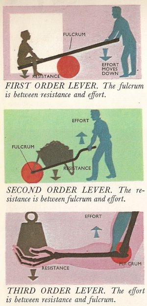
All levers belong to one of three classes or orders, depending on the relationship between the effort, load, and fulcrum – the pivot. In the seesaw arrangement of the first order (top diagram) the fulcrum is between the load and the effort. In the second class of levers (middle diagram) an upward effort raises a load placed between effort and fulcrum. A wheelbarrow uses this principle. In the third order (bottom) the effort acts between the fulcrum and the load. Many hydraulically operated machines use leverage of this order and some complex machines – such as printing presses – have all the orders of levers somewhere in their mechanism, as have the limbs of the human body.
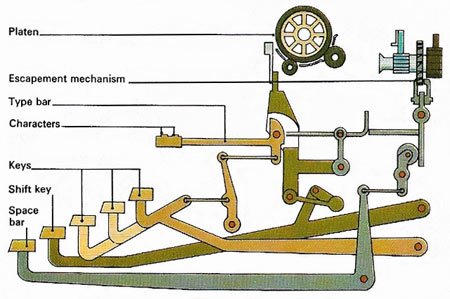
A typewriter's keys are operated through a series of linkages acting as levers. As a key is tapped, the levers move a type bar and make a character print on paper wrapped round the platen. Pressing the space bar releases an escapement mechanism to advance the carriage without a character being typed. The levers controlled by the shift key raise the whole lever system so that, on tapping a type key, the lower character on the type bar makes contact with the typewriter ribbon and prints on the paper. Other levers are used to move the carriage sideways and work the tabulator controls.
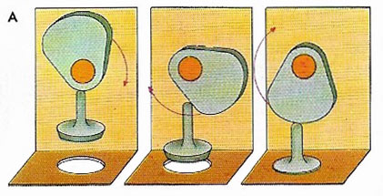
A disc cam (A) can be regarded as a lever of variable length that changes rotary motion into an up-and-down or side-to-side reciprocating motion. Disc cams are commonly used to permeate the valves in a car engine.
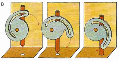
The rotary motion of a slot cam (B) drives a vertical arm up or down – or a horizontal one side-ways. Using such a cam, a twisting movement can produce linear motion to work the bolt on a lock.
Levers form one of the most important groups of simple machines, devices that enable energy to be used in the most advantageous way. At its simplest a lever is a rigid bar that can be turned freely round a fixed point (known as the fulcrum), and it is surprising what such a simple device can achieve. Given the right conditions a person could, for instance, lift a car on their own.
Three terms need to be explained in discussing levers. The load which is lifted or moved is referred to as the resistance. The force used in moving it is called the effort – both of these may be measured in newtons (N). The mechanical advantage is the ratio of the resistance to the effort. Expressed as a formula: mechanical advantage = resistance/effort.
For example, if an effort of 100 N has to be applied to a lever to raise a load (resistance) of 300 N, the mechanical advantage of that lever would be 3. The larger the mechanical advantage, the greater is the resistance that can be moved by the lever with the same effort. It must be emphasized, however, that neither levers nor any other kind of machine can create energy (indeed they tend to waste it) – they merely enable it to be used to better advantage.
For convenience levers are often divided into three orders or classes: the first, the second, and the third. In fact there is no actual difference in the principles by which they work, and similar calculations can be applied to all of them. The distinctions between them are concerned with the relative positions of the fulcrum, the effort, and the resistance.
Orders of levers
First order
The first order of levers has the fulcrum (pivot) in between the resistance at one end at the effort at the other. A simple example is the seesaw (teeter-totter). Using this type of lever we can lift objects that normally we'd find difficult if not impossible to move. As the diagram shows, the resistance and the effort move in opposite directions, one up, the other down. Now if the fulcrum of the lever is exactly halfway between effort and resistance the mechanical advantage will be 1 (i.e., a certain amount of effort is required to move an equal amount of resistance). If, on the other hand, the fulcrum is nearer to the resistance than it is to the effort there will be a greater mechanical advantage. From this it can be seen that a vital factor in the design of a lever is how far the resistance and the effort are from the fulcrum. The equation governing this factor is:
Resistance × distance from resistance to fulcrum = effort × distance from effort to fulcrum
If the resistance is great, then the fulcrum must be nearer to it than to the effort. This equation applies to all kinds of levers.
If the resistance is tending to pull the lever in a clockwise direction, then the effort will be pulling it in an anticlockwise direction. The two will be exerting opposing turning effects, or moments. (Moment equals the force applied multiplied by the perpendicular distance from the line of action of the force to the fulcrum.) For the two moments to balance each other the moment of the resistance must equal the moment of the effort. This is just another way of expressing the equation stated above. For the effort to actually move the resistance, a slightly greater effort will be required.
Second order
The second order of levers has the fulcrum at one end and the effort at the other, with the resistance in the middle. An everyday example is the wheelbarrow (complicated slightly by the addition of a wheel at the fulcrum). The load can be raised by lifting the handles of the barrow. Here again the mechanical advantage is greater the longer the distance between fulcrum and effort and the shorter the distance between fulcrum and load.
Third order
The third order of levers has the least mechanical advantage of all, and in fact a greater effort is needed than the amount of resistance moved. Here the fulcrum is at one end and the resistance at the other, with the effort in between. The human arm uses this type of leverage, with the elbow as the fulcrum, the resistance held in the hand and the effort applied by a contracting muscle in the upper arm attached to the forearm.
Something for nothing?
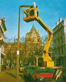 |
| Tall structures such as street lamps can be reached for cleaning and maintenance using a "cherry picker" with hydraulically operated levers, often mounted on a truck. Similar vehicles are used by fire brigades to provide a high vantage point for hoses or for rescuing people trapped in tall buildings. Hydraulic linkages can work such hinged joints in much the same way as muscles bend a man's arm at the elbow; both are examples of the third order of levers. Because the effort is applied so close to the fulcrum (pivot), a large effort is required to move and load at the end of its long arm. This is why engine-powered hydraulics have to be used.
|
Levers don't create energy. How then do they succeed in moving greater loads than is otherwise possible? The answer is that if they move a greater load they do not move it so far as they would if the effort was applied directly. Thus a person using a force of 100 N to raise a resistance of 300 N will raise it only 1 centimeter for every 3 centimeters they push on the lever. In the case of levers where there is a mechanical disadvantage (i.e., the effort has to be greater than the resistance) the resistance is moved more than the effort.

