
linear accelerator
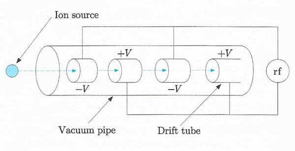
Figure 1. Acceleration in a linear proton accelerator.
In a linear accelerator (or linac) for accelerating protons, the particles pass through a series of metal pipes called drift tubes that are located in a vacuum vessel and connected successively to alternate terminals of an rf oscillator, as shown in Figure 1. The positively charged particles accelerated by the field move towards the first drift tube. If the alternator can change its direction as the particles pass through that tube, then they will be accelerated again on their way between the exit of the first and entry to the second tube, and so on. Thus the particles will form bunches and their final energy will be the sum of the energies received at the gaps between the drift tubes. Because the particles are accelerating their speed is increasing, and hence the lengths of the drift tubes have to increase to ensure continuous acceleration. To produce a useful beam, the particles must keep in phase with the rf field and remain focused. Proton linacs of this type are often used as injectors; that is, they produce protons of moderate energy that are then injected into a more powerful machine, often a synchrotron, where they are accelerated to much higher energies. An example is the linac at J-PARC (Japan Proton Accelerator Research Complex), which accelerates protons to an energy of 3 gigaelectronvolts (GeV) before they are injected into the main J-PARC ring, where they are further accelerated to 50 GeV.
For electrons, a variation of this method is used. In this case the accelerator consists of a straight tube in the form of a series of cylindrical metal cavities. Power is fed to the accelerator from a series of devices called klystrons, which produce electromagnetic radiation in the form of microwave pulses that are transported via waveguides to the accelerator. There they generate an oscillating electric field pointing along the direction of the metal tube and a magnetic field in a circle around the interior of the accelerating tube. The magnetic field helps to keep the beam focused, and the frequency of the microwaves is adjusted so that the electrons arrive at each cavity in the accelerator at the optimal time to receive the maximum energy boost from the electric field. As long as this phase relationship can be maintained, the particles will be continuously accelerated. The largest electron linac built was at the SLAC laboratory in Stanford, California. This accelerator consisted of 80 000 copper cavities separated by copper disks with a small hole at the centre to transmit the beam and was over 3 kilometers long. It could accelerate electrons and positrons to a maximum energy of 50 GeV, but was closed after a series of historically important experiments in 2008.
An ingenious way of reducing the enormous lengths of high-energy linacs has been developed at the Continuous Electron Beam Accelerator Facility (CEBAF) at the Jefferson Laboratory in the USA. This utilizes the fact that, above about 50 MeV, electron velocities are very close to the speed of light and thus electrons of very different energies can be accelerated in the same device. Instead of a single long linac, the CEBAF machine consists of two much shorter linacs and the beam from one is bent and passed through the other. This can be repeated for up to four cycles. Even with the radiation losses inherent in bending the beams, very intense beams can be produced with energies between 0.5 and 6.0 GeV. CEBAF has proved to be an important machine for studying the details of nucleon structure.

