
electrical circuit
An electrical circuit is an assemblage of electrical conductors (usually wires) and components through which current from a power source, such as a battery or generator flows. Components may be connected one after another (see series circuit) or side by side (see parallel circuit). If current is able to flow between two points their connection is a closed circuit; if not, an open circuit; and if resistance between them is virtually zero, a short circuit: a electric switch when off is a closed circuit, when on is a short circuit. Short circuits between the terminals of a power source are dangerous (see circuit breaker; fuse). See also Kirchhoff's laws.
Analysis of electric circuits
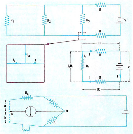
The analysis of electric circuits, to find the voltages and currents at every point, employs two basic laws, illustrated here. The circuit shown supplies power from a battery (V) to three components (having resistance R1, R2, R3) through power lines which each have a resistance (R). First, Kirchoff's "current law" states that at every junction, electric current neither appears nor vanishes: current is conserved, thus (center left) I = I3 + I2; and so on around the circuit. Second Kirchoff's "voltage law" states that the total voltage around any constituent circuit is zero: thus (center right,applying Ohm's law) V + IR + I3R3 + IR = 0; the same applies to the other two circuit loops. Given the battery voltage and the resistances, the currents can be calculated. The bottom diagram shows the circuit of an electrical resistance thermometer, in which changes in the probe resistance, r, are used to measure the temperature. Contact C is moved along a resistance-wire (ab) until the detector in CD shows zero current. If the two resistances R are equal, it is then true that Rc + a = b + r; r is read off from a pre-calibrated scale along the wire ab.

