
wind tunnel
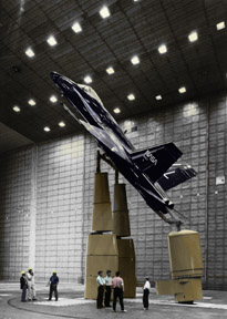
F-18 being prepared for wind tunnel test.
A wind tunnel is a device used to investigate the aerodynamic properties of objects by passing a stream of velocity-controled air over them. The heart of the wind tunnel is the test section where a scale model is supported in a carefully controlled airstream that produces a flow of air about the model that duplicates the full-scale aircraft. Appropriate balances and test instrumentation measure the aerodynamic characteristics of the model and the field around it (its flow field). Although the form of a wind tunnel can vary, all wind tunnels have a drive system, a test section, use a model that is supported in an airstream and whose characteristics are measured by test instrumentation. The wind tunnel allows the aerodynamic forces of lift, drag, and side force in reference to the tunnel axis (the axial center-line of the test section) to be measured.
First wind tunnels
Beginning in the mid-1700s, hopeful airplane designers realized that, if they were to build aircraft that would fly, they needed to understand how air moved over aircraft surfaces. Although they observed birds and tried to pattern their aircraft after bird flight, these aircraft uniformly failed. Bird flight did not provide the data they needed. They recognized that, to get the necessary data, they had two choices: they could move their test aircraft through the air at the required velocity or they could blow air past a stationary model. The whirling arm was early researchers' attempt at the first method.
The English mathematician Benjamin Robins used a whirling arm in his experiments in 1746. Robins mounted variously shaped objects on the tip of the arm and spun them in different directions. He found that the shape of the object seemed to affect the air resistance, or drag, even though equal total areas were being spun and were exposed to the airstream. He realized that the theories of Sir Isaac Newton did not adequately describe the complex relationship between drag, the shape and orientation of the object, and air velocity. However, his whirling arm could reach speeds of only a few feet per second, which limited his experiments. Soon after, another Englishman, John Smeaton, adopted Robins' invention of the whirling arm to test the forces exerted by air and water on windmill blades.
Sir George Cayley also used a whirling arm to measure the drag and lift of airfoils. His whirling arm was five feet (1.5 meters) long and attained top speeds of about 10 to 20 feet per second (3 to 6 meters per second). Cayley's 1804 unpiloted glider was built and flew successfully based on test data gathered from his whirling arm.
Otto Lilienthal's glider experiments were preceded by his whirling arm tests of various lifting surfaces. Between 1866 and 1889, he built several whirling arms, ranging from 6.5 to 23 feet (2 to 7 meters) in diameter. However, the tests he carried out with these arms gave incorrect results for both flat and cambered airfoils and led him to believe that powered flight was highly unlikely.
Hiram Maxim also used a huge whirling arm to test airfoils. His whirling arm included elaborate instruments to measure lift, drag, and relative air velocity. Samuel Langley, the mathematician, astronomer, and secretary of the Smithsonian Institution, was another who experimented using a whirling arm before he built his aerodromes. His whirling arm was 60 feet (18 meters) in diameter and its 10-horsepower (7.5-kilowatt) engine could accelerate it to speeds of 100 mph (161 kilometers per hour). But his results were thrown off by the winds and turbulence that the arm itself created.
The whirling arm provided a good deal of the aerodynamic data through the end of the 19th century. However, it had limitations. Basically, it was imprecise so the results it produced were also imprecise. For instance, the arm stirred up the air with its motion so that both the arm itself and the air it went through were moving. Experimenters could not determine the true relative velocity between the aircraft model and the air through which it moved. It was also very difficult to mount instruments on the arm so that the forces exerted on it could be measured at the same time that it was spinning at a high speed.
So experimenters took another tactic – that of blowing air past a stationary model – and began looking for a dependable way to do this. The wind tunnel was the result. This apparatus solved most of the problems associated with the whirling arm. Once researchers realized its potential, they eliminated the whirling arm from their repertoire of experimental tools.
Frank H. Wenham was the first individual to design a wind tunnel. He was a self-taught British engineer whose interests spanned a wide range of engineering applications. A charter member of the Aeronautical Society of Great Britain, he lectured frequently to the Society. He persuaded the organization to raise the funds needed to build a wind tunnel, which was constructed in 1871. Wenham designed the apparatus and was the first to use it. John Browning, an optician and another member of the group, built the tunnel, which was located at Penn's Marine Engineering Works at Greenwich, England.
The tunnel was 12 feet (3.7 meters) long and 18 inches (45.7 centimeters) square. A steam-powered fan drove the air through a duct to the test section where the model was mounted. The air could travel at a maximum velocity of 40 mph (64.4 kilometers per hour). It was an unsophisticated device – it had an unsteady airstream that made accurate measurements that could be replicated almost impossible – and had no vanes for guiding the air. Nevertheless, it yielded important results.
Wenham mounted various shapes in the tunnel and measured the lift and drag forces created by the air that rushed by the shapes. Results showed that at low angles of incidence, the relationship of lift to drag of the test surfaces (the lift-drag ratio) was higher than expected at a low angle of attack. With such high lift-to-drag ratios, wings could support substantial weights, making powered flight seem more attainable than previously thought. The research also showed that long, narrow wings, called high-aspect-ratio wings, provided much more lift than stubby wings with the same area.
Hiram Maxim also built a wind tunnel when he realized that his whirling arm had limitations. His wind tunnel was also large – 12 feet (3.7 meters) long and with a test section 3 feet (0.9 meter) square. Twin fans blew air into the test section at 50 mph (80.5 kilometers per hour). The tunnel and whirling arm proved to Maxim that cambered airfoils provided the most lift with the least drag. He was also the first to understand that the total drag produced by a structure was greater than the sum of the drags of the individual components – called aerodynamic interference. This concept was demonstrated in 1894 when the huge aircraft he built and "flew" developed so much lift that it tore loose from its test track and destroyed itself.
In the early 1880s, Horatio Phillips tried to carry out tests similar to Wenham's with his own wind tunnel. His tunnel was a box 6 feet (1.8 meters) long and 17 inches (43 centimeters) on each side. He directed a jet of steam through the box, blasting a series of wing shapes that he placed inside the tunnel. He hoped to find out how fast the velocity of the oncoming airstream needed to be so that each different form, which carried equal weights, would remain suspended in the airflow.
In his tunnel, Phillips eliminated the problems associated with airflow fluctuation that troubled Wenham by using a steam injection system to generate the airflow. The air would be sucked through the entrance into the tunnel. It then went through a narrow area called a throat that was in the center of the tunnel and which reduced the flow area. The aerodynamic model to be tested was mounted in the throat area, and the flow velocity would be greatest there – up to about 41 mph (66 km/h). Although an improvement over Wenham's box, Phillips' tunnel was still fairly primitive. But it did provide data that allowed Phillips to build the aircraft he used in his attempts to fly.
Soon after Phillips conducted his experiments, another European, this time the Frenchman Gustave Eiffel, would conduct experiments using a wind tunnel. And in the United States, the Wright brothers would design and use a wind tunnel that would prove instrumental in the success of the first flying machine.
Evolution of the wind tunnel
Not every piece of aviation-related technology is actually part of the airplane. Many important technological developments that either support aircraft operations or support the design of aircraft never leave the ground. Wind tunnels are an excellent example of a technological innovation that supports aircraft design. Wind tunnels have enabled designers to develop many of the major early aviation technologies, such as the low-drag cowling, more efficient airfoils, retractable landing gear, anti-icing equipment, and better propellers and engines. Wind tunnels themselves eventually became complicated pieces of technology. They are not simply a tube or box with a fan blowing air but are carefully designed and constructed (and often very large) laboratory instruments. Without constant improvements in wind tunnel technology, aeronautical research would have ground to a standstill decades ago.
Early aviation researchers realized that they could test their craft by flying them or by flowing air past them. The earliest experimenters used a whirling arm to fly a craft under controlled conditions. But problems that others had encountered with the whirling arm convinced the Wright brothers in 1903 that they should use a wind tunnel rather than a whirling arm as their primary test device. They developed an early wind tunnel in their laboratory.
For approximately the next two decades, wind tunnels were built in Europe but very few were built in the United States. Albert Zahm, a professor at Catholic University in Washington, DC, built an impressive wind tunnel in 1901 with the support of a wealthy industrialist. Zahm's wind tunnel had many advanced features such as special devices and structures to straighten the airflow and extremely sensitive pressure gauges. He made some important contributions to aerodynamics, such as proving that the friction of air over an aircraft's skin was a major cause of drag at subsonic speeds. But his financial supporter died, the money dried up, and Zahm's work stopped in 1908. A few years later, he built an 8-feet × 8-feet (2.4-meter × 2.4-meter) tunnel at the Washington Navy Yard that allowed models to be tested at speeds of 160 mph (257 kilometers per hour), which many military aircraft could reach in a dive.
While American wind tunnel research stagnated, the European wind tunnels developed between 1903 and the start of World War I grew increasingly larger and more sophisticated. For instance, Gustave Eiffel, who built the famous tower in Paris, built a private aerodynamics laboratory with his own money and constructed several wind tunnels. Many of these early wind tunnels, however, were simply a long tube with a propeller mounted inside, usually behind the section for mounting the model.
In 1908, Ludwig Prandtl built the first wind tunnel of "continuous circuit" design, which meant that the tunnel's front and back were connected, like a racetrack. He used vanes at the corners of the tunnel to turn the airflow and screens and honeycomb structures to smooth the flow. This made the tunnel very efficient. In 1916 Prandtl built his second-generation wind tunnel, which serves as the basis for virtually all modern wind tunnels. In this kind of tunnel, the tunnel's cross section becomes larger as the air comes closer to the testing area (which means that you can look at the exterior of a wind tunnel and tell which way the air flows inside). The tunnel includes a "stilling chamber" just before the section where the air reaches the model. This chamber reduces turbulence. The air is then sped up by entering a contracting cone or nozzle.
In 1920, the National Advisory Committee for Aeronautics (NACA) completed its first wind tunnel at Langley Field, Virginia. It was essentially a copy of a decade-old English wind tunnel and did not perform much useful research, but it allowed NACA engineers to understand the problems associated with building and operating a wind tunnel.
By 1921, more than 20 wind tunnels were in operation throughout the world, but all operated at normal atmospheric pressures. However, Osborne Reynolds had shown that airflow conditions could be radically different for model and full-scale aircraft. One way to compensate for this was to build large tunnels able to hold full-size aircraft, but this was expensive and impractical. Another way to compensate was to build a wind tunnel that could operate at high pressures. A subscale model tested at higher pressures could provide the same exact data as a full-scale model tested at normal atmospheric pressure. In 1921, the NACA started work on the Langley Laboratory's Variable Density Tunnel (VDT), which placed the wind tunnel inside a strong pressurized tank. The VDT became operational in 1923 and quickly became the primary source of aerodynamic data for high Reynolds numbers. It was the most advanced wind tunnel of its day and helped the United States become a leader in aeronautical research.
The NACA developed the Propeller Research Tunnel (PRT) at Langley that became operational in 1927. This was a huge tunnel for the day and had a nozzle with a throat diameter of 20 feet (6 meters). It allowed NACA engineers to test full-size aircraft fuselages, with their propellers attached. Using the PRT, researchers soon realized that landing gear and the engine cylinders of airplanes caused tremendous drag and led them to develop the low-drag cowling and retractable landing gear.
In 1927, the NACA also started work on its first high-speed wind tunnel (HST). Although most aircraft flew no more than 200 mph (322 kilometers per hour) at this time, their propeller tips approached the speed of sound. Some racing planes were also reaching about Mach 0.5 and a few aerodynamicists realized that planes would continue to go faster. The first HSTs were small and could test models that were only a few inches long. By 1936 a Langley HST entered service with a diameter of 8 feet (2.4 meters) capable of producing airspeeds of Mach 0.75 (575 mph) (925 kilometers per hour). By February 1945, this tunnel was achieving airspeeds of Mach 1. The tunnel demonstrated that rivet heads and other irregularities on the surface of an airplane created much drag, leading designers to switch to new methods that did not produce protrusions affecting the airflow.
One big question for many of these early tunnels was how to mount the model. There were two main problems associated with this. First, how could the model be mounted so that accurate readings could be taken? Second, how could the model be mounted without affecting the test data? Some early tunnels mounted the models upside down, on wires. It was easier to measure lift, which in this case pulled the plane down toward the ground (with the wing upside down, the areas of low and high pressure were reversed, pulling the plane toward the ground rather than away from it). Another development was the "stinger," which was a metal pole that stuck out from the top or bottom of the tunnel and into the rear of the model. By being located behind the model, this reduced its interference with the airflow, although it still had some effect. Later on, even less intrusive methods of supporting a model were developed, although they too had their limitations.
Advanced wind tunnels
By the late 1940s, aircraft were becoming increasingly expensive to develop and the costs of designing an unsuccessful aircraft were also growing. As a result, aircraft designers sought to model mathematically and to simulate as much of an aircraft's performance as they could without having to build the airplane itself. This, combined with the increasing speed of aircraft, created a great demand for new and more sophisticated wind tunnels. In particular, supersonic wind tunnels were in great demand during the post-World War II period.
Supersonic tunnels work in a way that seems contrary to logic. As the throat of a wind tunnel constricts, one expects the velocity of the air rushing through it to increase. It therefore seems logical that a model should be placed at the constricted part of such a tunnel in order to take advantage of the high-velocity airflow. But the reality is that as the airspeed approaches Mach 1, the air compresses and also heats up as it piles up at this constricted part. Only when the air gets past this constriction does it actually move faster than Mach 1, as the energy stored in both the compression and in the heat of the air converts to kinetic energy. Put another way, all of this stored energy has to convert to another form and this form consists of large amounts of air moving very fast through the wind tunnel. This is how a supersonic wind tunnel works, with the model placed in a section of the tunnel where the throat actually expands.
Numerous small supersonic tunnels were in use by the 1940s, but aircraft designers wanted bigger tunnels for their models. By 1948, NACA began operating a 4-ft by 4-ft (1.2-m by 1.2-m) supersonic tunnel at Langley, Virginia, on the Atlantic coast. Another NACA facility, Ames, in California, also began operating a slightly larger and more sophisticated supersonic wind tunnel around this time. Because even the slightest imperfection in the tunnel walls would cause the air to pile up and create shock waves, supersonic tunnels require very smooth interior surfaces.
Many of the same principles used in supersonic tunnels were also used in hypersonic tunnels to explore speeds greater than Mach 5. But several other problems occur in these types of tunnels. One is that the power requirements to accelerate the air are tremendous, so most hypersonic wind tunnels do not operate continuously but store up tremendous amounts of compressed air and release it in a brief burst. This is why many hypersonic tunnels have large storage tanks for holding compressed air. Another problem is that as the air moves out of the constriction chamber it cools as its heat energy is converted to kinetic energy. In a hypersonic tunnel, the air can cool so much that it actually liquefies. This is not simply a case of the moisture in the air condensing. The air itself turns to liquid. In order to prevent this from happening, the air is deliberately heated as it is compressed in a "settling chamber" before being released. In a Mach 10 wind tunnel, for example, air is heated to 3,000°F (1649°C) so that it does not liquefy when it is released.
Another method of obtaining high velocities is to fire models out of the barrel of a gun inside of a supersonic wind tunnel. In this way, the speed of the model combines with the speed of the moving air to produce a greater simulated velocity. The models are photographed as they streak by. Because the air itself is not moving at hypersonic velocities, this does not create any of the problems associated with liquefication of the air, but the models are destroyed in the process of testing them.
A major development during this period was the slotted wall wind tunnel. A big problem with wind tunnels is that the air flowing off a model can hit the tunnel wall, and flow back toward the model and/or interfere with the test measurements. Ray Wright, a researcher at Langley, proposed putting slots in the walls of a wind tunnel so that the air could move more freely around the model. Another group of aerodynamicists, led by John Stack, applied this technique to the transonic wind tunnel, which instantly solved many of the problems that they were encountering as air speeds approached Mach 1. As a result, in 1951 Stack and his group were awarded the Collier Trophy, which honors the most important advance in aeronautics for the year.
In addition to being used to design new planes, wind tunnels are also used to solve many other problems that affect existing aircraft once they become operational. One problem that plagues aircraft that fly in cold temperatures is ice. Ice builds up on propellers and on aircraft surfaces, particularly wings, and can affect performance in dangerous ways. Ice buildup on wings is particularly bad, for it can destroy lift and cause the plane to lose altitude and crash, or can block control surfaces and make it impossible for the pilot to fly the plane.
Icing tunnels were developed beginning in the 1940s to study this problem. They are similar to conventional subsonic wind tunnels but are equipped with refrigeration systems that can cool the air to well below freezing. Water droplets are then sprayed into the airflow so that they can freeze on aircraft surfaces. Engineers monitor the buildup of ice on the aircraft. Anti-icing devices such as electric heaters or pipes containing a heated liquid such as alcohol are installed in the parts of aircraft that generate the most ice. When ice begins to build up on a model in the icing tunnel, the heaters are turned on and researchers then study how effective they are at stopping the buildup of ice.
There are many other different kinds of wind tunnels. There are "spin tunnels" that test how aircraft behave when they fly out of control and start spinning, a situation that is commonly referred to by pilots as "departure from controlled flight." These tunnels test whether the pilot can recover in this situation or needs to parachute out of the airplane. There are "free flight" tunnels where models are actually "flown" by remote control by a pilot sitting in a control booth and sending signals to the model through a wire tether. There are also blast-furnace-type tunnels for testing how spacecraft and missiles act in high temperature airflows such as they encounter when reentering Earth's atmosphere. And there are magnetic tunnels, where the model is held stable inside the tunnel by powerful magnetic fields so that more accurate measurements can be taken.
Before the 1950s, most of the wind tunnels operated in the United States were run by the NACA. But in 1946, a study of American wind tunnels resulted in a recommendation that industry and universities play a greater role in operating wind tunnels. This led to the National Unitary Wind Tunnel Plan Act of 1949. The Act established new supersonic wind tunnels at the three major NACA facilities, but also pushed for the creation of supersonic wind tunnels at universities. The development of a university wind-tunnel base was important both to serve as a check on NACA research and to train new aeronautical engineers. The NACA tunnels were also directed to perform more industry research, symbolizing a decreased emphasis on government-sponsored wind tunnel research.
For years wind tunnels represented a less expensive way of testing an airplane than building the full-size vehicle. But wind tunnel research was and still is expensive. Testing a new airplane design in a wind tunnel costs millions of dollars. As a result, aircraft designers have increasingly shifted to computers and a method called computational fluid dynamics (air, after all, is a fluid, like water), which simulates airflow entirely within a computer. Computing power is relatively cheap, and computer models can be changed much more easily than physical models made of plastic, metal, and wood.
Today, wind tunnels are used less and less and the giant wind tunnels that dominated so many aeronautical research centers starting in the 1930s and 1940s are now often called upon only to serve as backups to the computer simulations, to prove that their predictions are sound. In several important cases, however, aircraft designers have had to use wind tunnels to test their designs after computer simulations have proven inadequate. For example, the Pegasus XL air-launched rocket suffered an in-flight aerodynamic failure that was not predicted by a computer-generated aerodynamic model. But in a matter of years, most of the large NACA-built wind tunnels may become totally silent, their roar replaced by the hum of a supercomputer.

